1 minute read
Removing the LCD Module


IMPORTANT: Cable paths and positioning may not represent the actual model. During the removal and replacement of the LCD Module, ensure all available cable channels and clips are used and that the cables are replaced in the same position. NOTE: The following procedure outlines the steps to remove the LCD Module on models with 3G functionality. Models that do not support 3G do not require the removal of the yellow and blue Antenna cables detailed below. 1. See “Removing the Mainboard” on page 63. 2. The Lower Cover appears as follows when the Mainboard is removed. • Blue callout—Main 3G Antenna cable • Yellow callout—Aux 3G Antenna cable • Red callout—Main and Aux WLAN Antennas
3. Remove the Black and White WLAN cables from the cable clips as shown.
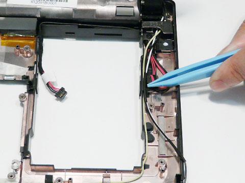

5. Remove the cable from the cable clips.


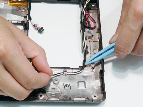
6. Remove the blue 3G cable from the cable clips as shown.


Step
Size
LCD Module M2*4 4
Quantity Screw Type
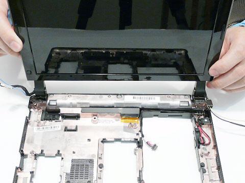
IMPORTANT: Ensure all cables are clear of the lower cover before removing the LCD module. 8. Grasp the module with both hands and lift upwards to remove the LCD Module.