7 minute read
DISASSEMBLY - FRONT SECTION REASSEMBLY - FRONT SECTION REASSEMBLY - AUXILIARY INTERMEDIATE HOUSING REASSEMBLY - AUXILIARY REAR HOUSING REASSEMBLY - COMPANION FLANGE AND CLUTCH HOUSING REASSEMBLY - SHIFTING CONTROLS


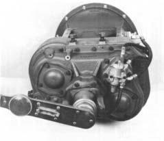
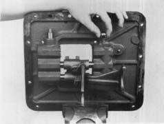
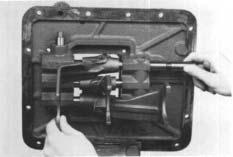
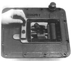
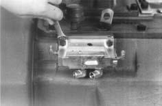
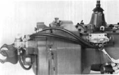
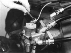
REASSEMBLY - COMPANION FLANGEAND CLUTCH HOUSING
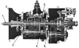
Companion Flange and Clutch Housing
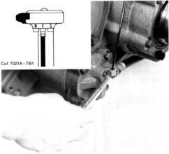
A. Installation of the Clutch Housing
1. Install the clutch housing on the studs in the front case.
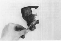
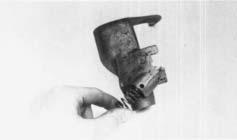
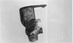
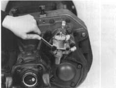
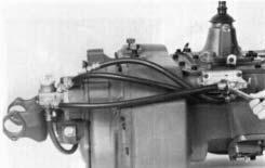
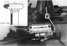
B. Installation of the Companion Flange or Yoke
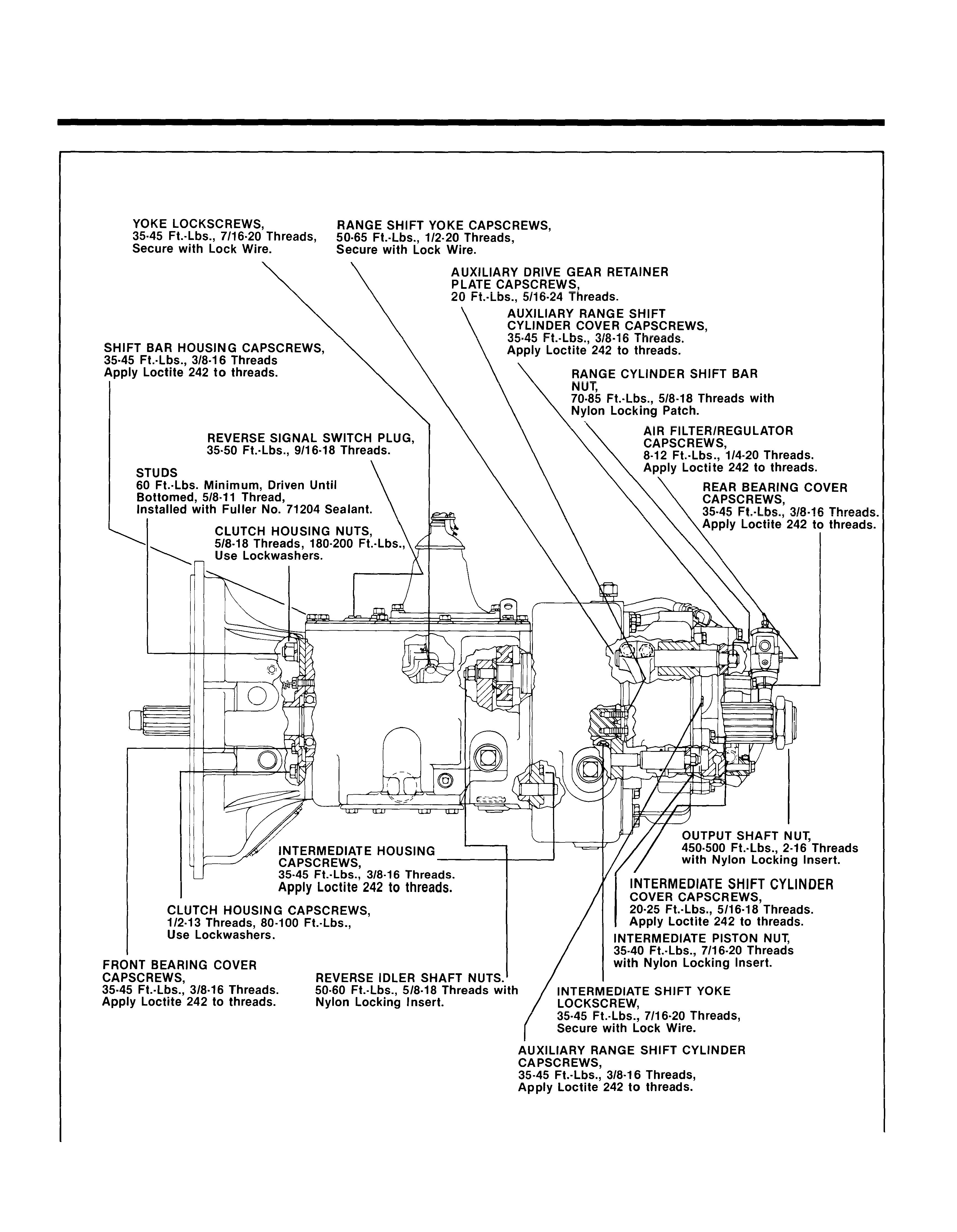
2. Install the washers and nuts on the studs and then install the washers and bolts, using correct torque:
See TORQUE RECOMMENDATIONS.
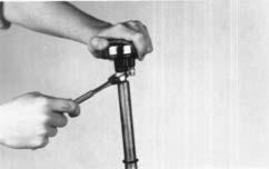
1. Install the speedometer drive gear or replacement spacer on the hub of the yoke or flange, lock the transmission by shifting the front section into two gears and install the yoke or flange on the splines of the tailshaft. Install the tailshaft nut and torque to 450-500 ft./lbs.
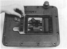
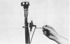
REASSEMBLY - SHIFTING CONTROLS
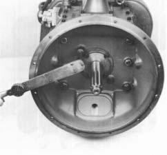
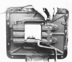
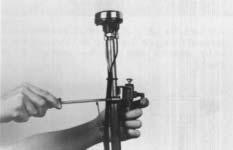
Shift Bar Housing

Keep the bar in the neutral position.
NOTE: Shift bar Iockscrews should be torqued to 40 lbs. ft. Overtorqueing Iockscrews may warp shift bars.
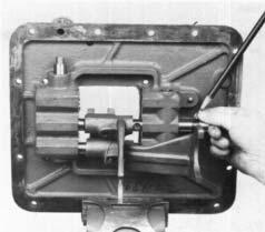
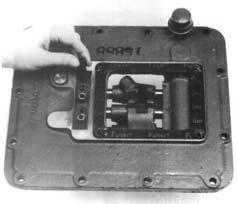
2. Install an interlock ball in the front web. 3. Install the actuating plunger in the rear web.
4. Install the 2nd-3rd speed shift bar and yoke, inserting the interlock pin in the bore of the neutral notch. Install the yoke Iockscrew and tighten and wire securely.
REASSEMBLY - SHIFTING CONTROLS
5. Install an interlock ball in the front web.
6. If previously removed, install the reverse-top plunger in the reverse yoke. Make sure that the plunger is fully seated in the bore.
7. Install the spring in the bore and on the plunger.
8.
Partially install the plug. Use the tip of the gear shift lever to push the plunger back into the bore to compress the spring. Tighten the plug fully and then back off 1/2 - 1 1/2 turns. Stake the plug threads in the hole.
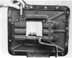
9.
Remove the assembly from the vise and install the three tension balls, one in each bore in the top of the housing.
10.
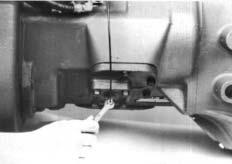
REASSEMBLY - SHIFTING CONTROLS
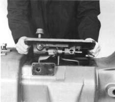
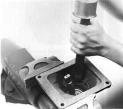
, Install the tension springs on top of the balls in 13. the bores. Check to make sure that the shift yokes and sliding clutches are in the neutral position and install the shift bar housing on the transmission, tension spring cover to the front and the yoke forks in the sliding clutches. Secure with the 13 capscrews.
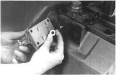
12. Install the tension spring cover and retain with the two capscrews.
REASSEMBLY - SHIFTING CONTROLS
Gear Shift Lever Housing Assembly
Reassembly and Installation
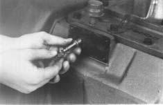
1. Install the spade pin or pivot pin, nut and washer in the borein the housing. If previously removed, install the O-ring in the groove.
Install the gear shift lever in the housing, fitting the slot in the lever ball over the spade pin.
Place the tension spring washer over the lever ball with the dished side up.
Seat the tension spring under the lugs in the housing, seating one coil at a time. Use of a spring driving tool is recommended.
Make sure that the three tension springs and balls are in the shift bar housing bores and install the gear shift lever housing and gasket on the shift bar housing.
REASSEMBLY-SHIFTING CONTROLS
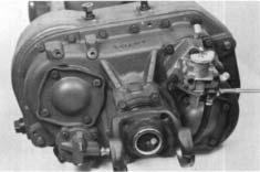
Air System
Installation of the Air System
NOTE: Installation procedure for air systems using the 3-position selector valve are shown. Refer to the Air System schematics for proper airline connections when an A-5015 Roadranger valve is used.
1. Install the actuating pin and spring in the bore in the case.
2. Install the hat-type alignment sleeve in the slave valve. 4. Attach the air filter/regulator assembly to the rear housing with the two retaining capscrews.
5. Connect the 1/4" air hose between the intermediate cylinder and the air filter/regulator assembly.
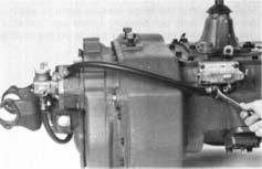
6. Connect the 1/4" I.D. air hose between the ñLî port of the slave valve and the direct range port of the range cylinder.
REASSEMBLY - SHIFTING CONTROLS
7. Connect the 1/4" I.D. air hose between the "H" port of the slave valve and the low range port of the range cylinder.
8. Connect the 1/4" I.D. air hose between the air filter/regulator assembly and the "S" port on the side of the slave valve.
9. Install the 1/8" O.D. air lines, sheathing and Orings on the shifting lever. Install the jam nut and selector valve and back the jam nut up against the selector valve to secure it in the desired position. NOTE: To avoid confusion, only the air line being installed in each of the following three steps is shown attached to the selector valve.
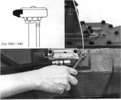
10. Connect the 1/8" O.D. white air line between the forward fitting on the slave air valve and the port in the selector valve identified with an "S". (See inset.)
Connect the 1/8" O.D. long black air line between the intermediate cylinder and the port in the selector valve identified with an "F". (See inset.)
12. Connect the 1/8" O.D. black air line between the rear fitting on the slave valve and the port in the selector valve identified with an "R". (See inset.)
If so equipped, attach the countershaft brake control valve and clamp to the shift lever and secure the valve by tightening the screw on the clamp.
Attach the black 1/8" O.D. brake control air line to the elbow fitting on the front of the valve and attach the white air line to the fitting on the bottom of the valve. 15. Attach the black 1/8" O.D. air line to the TCB-6 countershaft brake located on the right PTO opening.
16. Attach the white 1/8" O.D. air line to the top of the air filter/regulator.

Copyright Eaton Corporation, 2012. Eaton hereby grant their customers, vendors, or distributors permission to freely copy, reproduce and/or distribute this document in printed format. It may be copied only in its entirety without any changes or modifications. THIS INFORMATION IS NOT INTENDED FOR SALE OR RESALE, AND THIS NOTICE MUST REMAIN ON ALL COPIES.
Note: Features and specifications listed in this document are subject to change without notice and represent the maximum capabilities of the software and products with all options installed. Although every attempt has been made to ensure the accuracy of information contained within, Eaton makes no representation about the completeness, correctness or accuracy and assumes no responsibility for any errors or omissions. Features and functionality may vary depending on selected options.
For spec’ing or service assistance, call 1-800-826-HELP (4357) or visit www.eaton.com/roadranger. In Mexico, call 001-800-826-4357.
Roadranger: Eaton and trusted partners providing the best products and services in the industry, ensuring more time on the road.
Eaton Corporation
Vehicle Group P.O. Box 4013 Kalamazoo, MI 49003 USA 800-826-HELP (4357) www.eaton.com/roadranger Printed in USA
For parts or service call us Pro Gear & Transmission, Inc.

1 (877) 776-4600 (407) 872-1901 parts@eprogear.com 906 W. Gore St. Orlando, FL 32805