11 minute read
7.4 Standard Torque Values

from Dynapac Vibratory rollers CC425 Engine KOEL-4R1190NA1 CEV Stage IV Operating & Maintenance Manual

Use only the proper tools (inches) on hardware. Other tools may not fit properly and may slip and cause injury.
Head Markings
Fasteners should be replaced with the same grade or a higher grade. If higher grade fasteners are used, these should only be tightened to the strength of the original grade fastener.
Do not use these values if a different torque value or the tightening procedure is listed for a specific application. Torque values listed are for general use only. All values are suggested maximum with dry plated hardware.
Make sure fastener threads are clean and you properly start thread engagement. This will prevent them from falling when tightening.
The following pages list the recommended tightening torques for the various size bolts used for the roller. Proper torque specifications should be used at all times.
Recommended Torques
This page lists the recommended tightening torques, in foot/pounds (ft·lb), for the various size bolts and nuts that are used. Proper torque specifications should be used at all times. Dry means clean dry threads and lube means a light film of oil. Excess oil in a threaded dead end hole can create a hydraulic lock giving false torque readings. Suggested assembly torque values are per engineering specifications.
Bolt dimensions M16 (PN 902889)
Strength class 10.9
Tightening torque 192 Nm, torque class 2 (Dacromet treated)
7.5 Maintenance as Required Service as Required
The preventive maintenance and service in this section requires attention on the need basis, before, during, and after the operation shift. This is in addition to the 8 to 10 hour daily routine maintenance procedures. Performance of this inspection can result in longer life and maximum productivity from the roller. Refer to the manufacturer’s service manuals for maintenance and service on the carrier.
Clean the Roller
Clean the complete roller weekly. Daily cleaning is required if material is adhering to the roller working parts.
• Make sure that the operator areas, steps, and grab rails are clean. Oil, grease, snow, ice, or mud in these areas can cause to slip and fall. Clean the boots of excess mud before getting in the roller.
• Thoroughly wash all fittings, caps, plugs, and the like with a nonflammable, nontoxic cleaning solution before servicing to prevent dirt from entering while performing the service.
• After cleaning, check for defects in the air cleaner ducts.
a. Check intake for accumulation of debris that could restrict air flow.
b. Check the air cleaner mounting hardware for security.
c. Check all hoses for cracks, chafing, or deterioration and replace at the first sign of probable failure.
Loose Bolted Connections
If any loose nuts or bolts are found during the frequent walk-around and the daily inspections, make sure they are properly torqued. Refer to 7.4 Standard Torque Values for the required torque for all bolt sizes and grades. Always replace selflocking nuts if they have been loosened.
Air Cleaners
The following are detailed instructions for performing routine maintenance procedures on the air cleaner.
Raw, unfiltered air can damage the roller. Never service the air cleaner while the roller is running.
Airborne dust may be hazardous. Wear proper personal protective equipment while handling air cleaners and elements.
Connections and Ducts
Check air cleaner and ducts for leaks before every shift, during every shift, and after every shift. Make sure all connections are tight and sealed.
N o t e Dust that gets by the air cleaner system can often be detected by looking for dust streaks on the air transfer tubing or just inside the intake manifold inlet.
Air Cleaner Pre-Cleaner
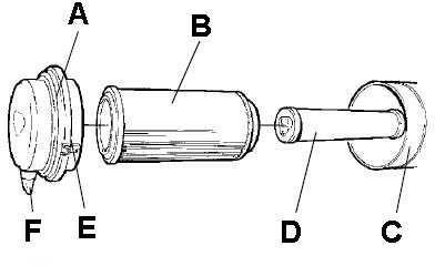
Wipe clean the inside of the cover and the filter housing. Wipe also both surfaces for the outlet pipe.
N o t e Check that the hose clamps between the filter housing and the suction hose are tight and that the hoses are intact. Inspect the entire hose system, all the way to the engine.
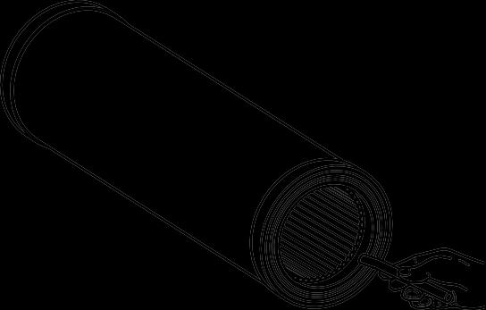
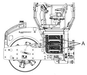
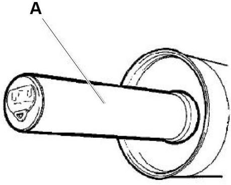
Figure 7-2: Air Cleaner Elements
Never clean Donoclone tubes with compressed air unless both the safety and primary elements are installed in the air cleaner. Do not steam clean the tubes in the pre-cleaner.
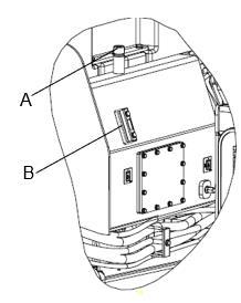
Air Cleaner Main Filter
The air cleaner is the dry type with two elements; a main filter that is replaceable and can be cleaned, and a backup filter that should only be replaced and never cleaned.
A Cover D Backup filter
B Main filter E Clips
C Filter housing F Dust valve
When the choking (air filter) indicator illuminates do the following maintenance steps.
1. Unclip the clamps holding the main filter.
2. Carefully withdraw the main filter.
N o t e Do not clean the air filter until the indicator illuminates on the control panel. Cleaning the filter when there is no indication is not recommended.
N o t e Make sure new elements arrive enclosed in plastic or in a protective membrane. Do not install elements that are unprotected. This is a dust hazard.
N o t e Never attempt to clean a backup filter. Change the backup filter whenever main filter replaced.
3. Examine the new or newly cleaned main filter for torn or damaged pleats, bent end covers, liners, and gaskets.
4. The backup filter should be replaced if the air cleaner indicator is red after servicing the main filter.
5. Clean the inside of the air cleaner housing before removing backup filter.
6. To replace the backup filter, remove the old filter from the holder. Dispose of the used element properly.
7. Install new backup filter into the holder.
8. Carefully install the cleaned or new main filter.
N o t e Replace air filter element after two cleaning interval
Air Circulation
Check that the engine has free circulation of cooling air through the grille in the engine compartment.
9. Re-install the back cover, make sure the dust valve is positioned downwards.
10. Inspect all air intake piping and joints between the air cleaner and inspect the air inlet to make sure that no dusty air can enter.
N o t e Never leave the air cleaner open longer than necessary.
N o t e The two most common servicing problems are over servicing and improper servicing.
Cleaning the Filter Element
Hose and Clamps
1. Periodic clamping bolts re-tightening is necessary due to cold-flow present in all rubber hoses. Tighten the boss clamps.
2. Examine and change out worn hoses and weakened Boss clamps. If hoses are to be changed out, change the Boss clamps also. Boss clamps hold the hose connections under a large amount of pressure. Boss clamps (including nuts and bolts) are for single use only. Do not reuse. Once removed, discard them.
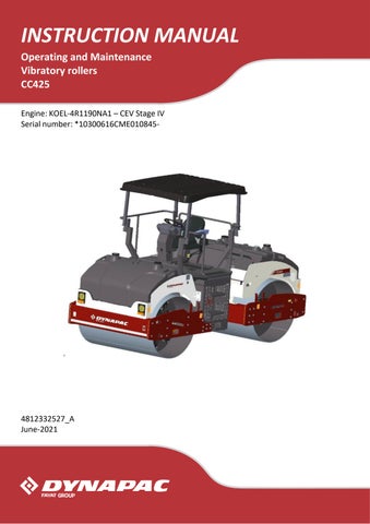
Clean the air filter element from inside to outside using compressed air.
Engine
Refer to the engine service and maintenance manuals for specific information on the engine maintenance.
N o t e Switch off the engine before filling the oil.
N o t e Care must be taken while draining the oil. Wear protective gloves and eye glasses.
1. Change the engine oil first 50 hours and then every 500 hours of operation.
2. Remove the oil filler cap and oil drain plug. Drain the oil into a suitable container.
3. Reinstall the drain plug and tighten.
4. Remove and replace the oil filter.
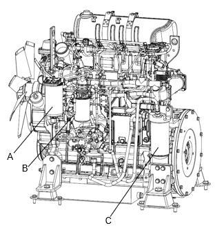
Figure 7-6: Fuel Filters
Batteries
The following battery maintenance must be carried out as part of the 250 hour routine maintenance schedule.
Batteries contain an acid and can cause injury. Skin and eye contact with battery fluid can cause injury. Avoid skin and eye contact with battery fluid. If contact occurs, flush area immediately with water.
Battery fumes can ignite and explode. Do not smoke when observing battery fluid level.
N o t e When disconnecting the battery, always disconnect the negative cable first. When connecting the battery, always connect the positive cable first.
N o t e Always wear protective glasses when working with batteries. Wash hands after touching batteries and connectors. Use of gloves recommended.
Batteries, Clamps, and Cables
The standard batteries supplied are heavy duty lead acid type, requiring the following maintenance.
1. Keep the top of the batteries clean.
2. Clean the terminals.
3. Keep battery connections tight.
A Main fuel filter
B Pre Fuel filter
C Engine oil filter
5. Remove the oil filler cap and fill the engine crank case with recommended oil.
6. Start the engine and allow it to idle for a few minutes. During this time, check around the oil filter and drain plug for leaks.
7. Install the oil filler cap.
4. Apply a small amount of grease to the terminal connections to prevent corrosion.
5. Inspect the cables, clamps, and hold down brackets. Replace if necessary.
Check Electrolyte Level
1. Shut off the engine.
2. Lockout/tagout the roller as per the site specific procedure.
3. Check the electrolyte level and keep the electrolyte level above the plates. Fluid level is low when below ring or ring is visible and too high when slots are not visible.
4. Refill with distilled water, if necessary.
Over filling can cause poor performance or early failure.
5. Remove lockout / tagout.
Fuel Tank
Refuel the tank every day before starting the roller.
1. Unscrew the lockable tank cap.
2. Fill diesel fuel to the lower edge of the filler pipe.
Check fuel tanks and fuel lines for possible leaks. Because of the potential fire hazard, leaks must be corrected as soon as they are spotted.
Fuel is flammable. May cause serious injury or death. Shut off the engine, extinguish all open flames, and do not smoke while filling the fuel tanks. Always wipe up any spilled fuel immediately.
• Check the fuel level by reading the fuel level gauge.
• Never allow fuel tanks to completely empty.
N o t e Fill tank with the correct grade of fuel. The fuel tank holds 250 liters.
Coolant System
Check that all hoses/hose connectors are intact and tight. Fill with coolant as specified in the lubricants specification.
Change the coolant every year. Failure to cool the engine properly can result in engine failure or severely reduce engine life.
Water Tank
Unscrewthe tank cap and fill with clean water. Do not remove the strainer. See technical specifications for the tank volume.
N o t e A small amount of environmentfriendly antifreeze is added.
Fixed Scrapers
Personal injury can occur when removing the radiator cap. Steam or fluid escaping from the radiator can burn. Inhibitor contains alkali. Avoid contact with skin and eyes. Wear protective gloves and eye glasses
Always shut off the engine and allow it to cool down before removing the radiator cap. Remove the radiator cap slowly to relieve pressure. Avoid contact with steam or escaping fluid.
Make sure that the scrapers are undamaged. Adjust the scrapers so that they are 1-2 mm from the drum. For special asphalt compounds, it may be better if the scraper blades lie lightly against the drums.
Asphalt remnants can accumulate on the scraper and affect the contact force. Clean as required.
1. Loosen the screws to adjust the contact pressure of the scraper blade against the drum.
2. Lock this setting by tightening the lock nut against the mounting plate.
3. Adjust the contact surface on both scraper attachments.
4. Tighten all the screws after adjustment.
Sprinkler System
Start the sprinkler system and make sure that nozzles are clogged. If necessary, clean clogged nozzles and the coarse filter located by the water pump.
The sprinkler system should be drained if there is a risk of freezing. Wear protective eye glases when working with compressed air.
Dismantle the blocked nozzle by hand. Blow the nozzle and fine filter clean with compressed air, or install replacement parts and clean the clogged parts later.
The scrapers must be lifted from the drum during transport.
Brakes
Run the roller very slowly forward. Hold the steering wheel firmly and brace yourself for a sudden stop. Press in the emergency stop. The roller will stop abruptly and the engine will switch off. After testing the brakes, set the forward/ reverse lever in neutral. Pull out the emergency stop. Start the engine. The roller is now ready for operation.
7.6Lubrication and Filters
Hydraulic Reservoir
The hydraulic reservoir oil level must be checked daily as part of the 8 to 10 hour routine maintenance procedure.
Excessive hydraulic oil can rupture hydraulic tank and cause injury or property damage.
N o t e Take extra care when working around or on the hydraulic system to make sure its complete cleanliness. When operating, the oil level must be between the maximum and minimum levels. Top up with hydraulic fluid as per lubricant specifications if level is too low.
N o t e Dirt in the hydraulic system will lead to premature component failure. A clean, contaminant free system is extremely important for the roller to function properly.
Check Hydraulic Oil Level
If the hydraulic oil level is low, add hydraulic oil.
1. Level the roller.
2. Check the reservoir oil level by viewing the sight gauge. Verify that fluid level is near the maximum level indicated on the sight glass.
3. Open the engine hood and unscrew the filler cap, top up with hydraulic fluid (as per lubricant specification) if the level is too low.
Steering Cylinder and Steering Joint
The steering cylinder is located under the operator platform. There is a grease fitting near the base and rod ends of the cylinder.
1. To access the four grease nipples, turn the steering wheel fully to the counterclockwise direction.
2. Wipe the grease nipples.
3. Apply five strokes of grease to each nipple using the hand-operated grease gun. Make sure that grease penetrates intothe bearing. If grease does not penetrate into bearings, it may be necessary to relieve the articulation joint with a jack while repeating the greasing process.
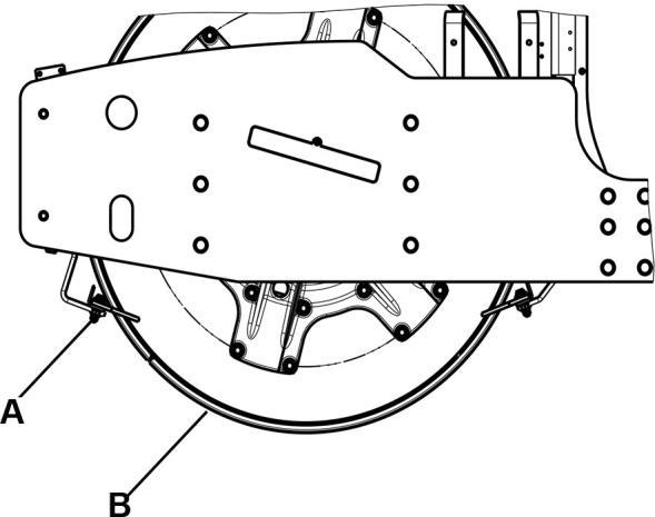
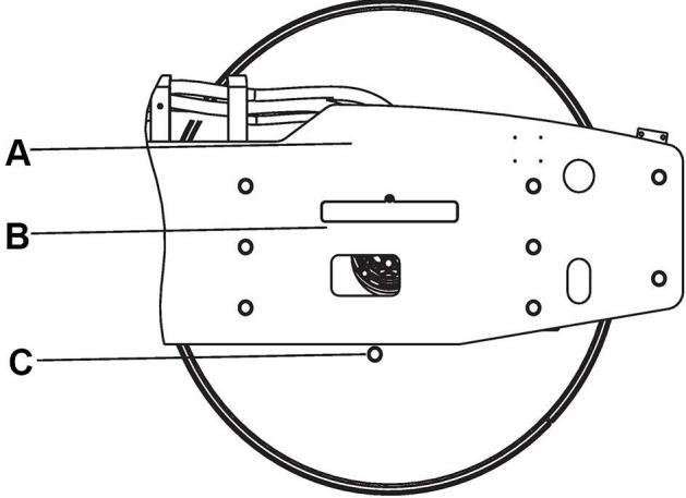
Drum - Oil Level
1. Run the roller slowly until the oil plug is opposite to one of the inspection holes.
2. Unscrew the plug and check that the oil level reaches up to the bottom of the hole. Top up with new oil if necessary. Use oil as per the lubricant specification.
3. Clean the magnetic oil plug from any metallic residue, and refit the plug.
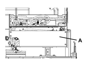
A Oil filling
B Oil level check
C Oil drain
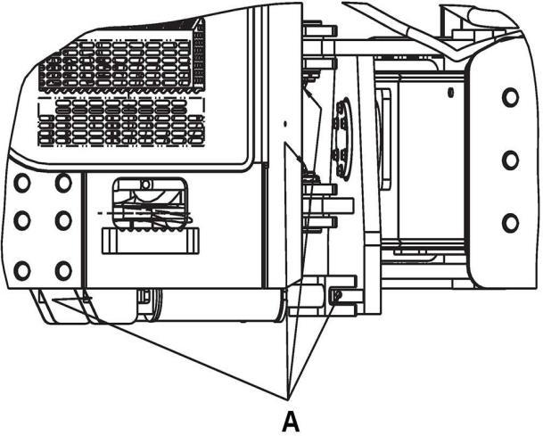
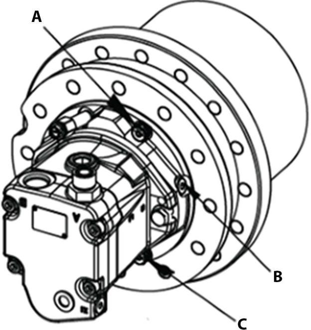
Check Drum Gear Oil Level
1. Move the roller until the inspection/filling holes are in position for filling.
2. Refill the oil about 1.1 L (0.3 gallons). Use transmission oil as per lubrication specification.
3. Make sure that oil level reaches up to the lower edge of the plug hole.
4. Clean and refit the plugs.
Housekeeping
The complete roller must be given a weekly cleaning. Daily cleaning will be required if material is adhering to the roller working parts.
1. Make sure the operator areas, steps, and grab rails are clean. Oil, grease, snow, ice, or mud in these areas can be slippery. Clean the boots of excess mud before getting in the cab or on the roller operator platform.
2. Check the tower feed installation for debris buildup around the sheaves.
3. Thoroughly wash all fittings, caps, plugs, and the like with a nonflammable, nontoxic cleaning solution before servicing to prevent dirt from entering while performing the service.
N o t e Protect all electrical components and control panels against entry of water or steam when using high pressure cleaning methods. Cover the fuel and hydraulic fill cap breathers located on each tank.
4. After cleaning, check for defects in the air cleaner ducts.
• Check intake for accumulation of debris that could restrict air flow.
• Check air cleaner mounting hardware for security.
A Oil filling plug
B Oil level plug
C Oil Drain plug
Controls
If the lever gets stiff after a prolonged period of use, remove the cover of the lever and lubricate.
Lubricate the forward/reverse lever in the engine compartment with a few drops of oil.
• Check all hoses for cracks, chafing, or deterioration and replace at the first sign of probable failure.