2 minute read
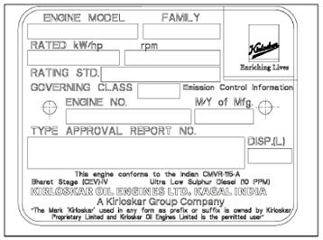
Engine Identification

from Dynapac Vibratory rollers CC425 Engine KOEL-4R1190NA1 CEV Stage IV Operating & Maintenance Manual

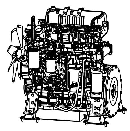
The engine identification plate is affixed to the right side of the engine. The engine identification plate provides model identification and other important data about the engine. Refer to the engine operation and maintenance manual for further information on the identification information. Have the following engine data available when communicating with an authorized repair location or engine dealer. The data on the engine identification plate is mandatory when sourcing service parts:
• Engine serial number
• Model
1.2 Roller Description
The roller is a two self-propelled vibratory tandem rollers in the nine-metric tonnes class featuring 1690-mm wide drums. The roller is equipped with drive, brakes, and vibration on both drums.
To permit optimum performance on a wide range of applications and site requirements, the roller is equipped with:
• Diesel engine
• Electrical system
• Propulsion system/transmission
• Brake system
• Secondary/parking brake
• Steering system
• Canopy
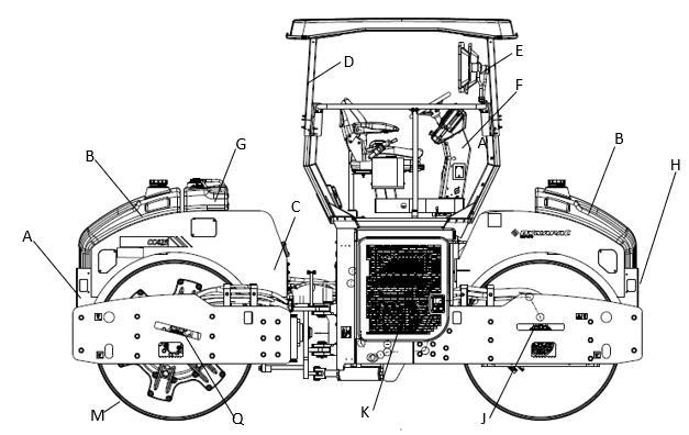
Identification of Major Components
Figure 1-6: Major Components Left Side
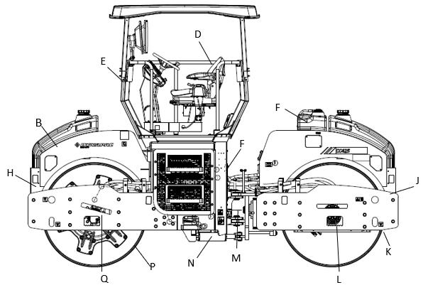
Diesel Engine
The roller is equipped with the water-cooled, straight four-cylinder BS IV diesel engine.
Electrical System
The roller is equipped with 12V DC electrical system and 90A alternator.
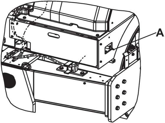
A Battery disconnector
Component Rating
Battery 12V, 150AH
Alternator 12V, 90amps
Starter 12V, 2.7kw
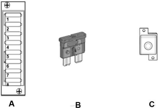
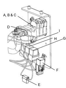
Main and Light Fuses
The main fuse and light fuse are placed near to a 100A starter relay on battery disconnector bracket.
A 10A -Fuse D and E 40A - Main and Light fuse
B 30A - Mini Relay F Battery Disconnector Switch
C 100A - Starter Relay
G 30A- Engine ECU fuse
F10 Main fuse 40 A
F11 Light fuse 40 A
F13 Engine ECU fuse 30 A
The flat pin, type C (medium) fuses and 20A fuse are used for driving lights.
Propulsion system/ Transmission
The propulsion system is a hydrostatic system with a hydraulic pump supplying two motors with gear box connected in parallel. The motors drive the front and rear drums.
The speed of the roller is proportional to the deflection of the control lever from neutral.
Brake system
The brake system consists of a service brake, secondary brake and parking brake. The service brake is hydrostatic and is activated by moving the control lever to neutral.
Secondary/Parking Brake
The secondary and parking brake system consists of spring multiple disc brakes in the drive gear box. The brakes are released with hydraulic pressure and are operated with a switch on the instrument panel.
Steering System
The steering system is a hydrostatic system.The control valve on the steering column distributes the flow to the control cylinder, which actuates the articulation.
The steering angle is proportional to the deflection of the steering wheel.
Roller Applications
The roller is built in accordance with international standards and recognized safety rules. Nevertheless, misuse may constitute a risk to the life and limb of the user or third parties, and may cause damage to the roller or other material property.
The roller must be used in accordance with its designated use as described in this manual. The roller must only be operated by trained, safetyconscious persons who are fully aware of risks involved in operating the roller. Any functional disorders, especially those affecting the safety ofthe roller, must be corrected immediately.
Designated Applications
The roller is designed primarily to compact thin and thick asphalt layers with respect to dual vibration amplitudes optimized for this purpose.
Non-Designated Applications
The roller is not designed to use as a ladder, support, or a work surface. it is not used to carry or transport passengers or equipment. The manufacturer/supplier cannot be held liable for any damage resulting from such use. The risk of such use lies entirely with the user.
Operating the roller within the limits of its designated use also involves compliance with the inspection and maintenance directives contained in the operating manual.