6 minute read
Functional Description – Keypad

from Dynapac Vibratory rollers CC425 Engine KOEL-4R1190NA1 CEV Stage IV Operating & Maintenance Manual

Working mode
Working lights
Sprinkler Manual/Auto
Horn
Symbol Designation Function
Work mode
Amplitude selector
Working lights
Sprinkler Manual/Auto
Sprinkler Timer
Engine speed selector
Amplitude, hight/low
Rotating beacon (Not Applicable)
Sprinkler Timer
Engine speed selector
LED OFF → Transport modeLED LEFT → Working mode, vibration Red
LED LEFT → Low amplitude Red
LED RIGHT → High amplitude
Turns on the working lights of canopy
LED OFF -
LED LEFT → Working lights, ON Red
LED LEFT → Sprinkler manual Red
LED RIGHT → Sprinkler auto Red
LED LEFT → Sprinkler spray low Red
LED CENTER → Sprinkler spray medium Red
LED RIGHT → Sprinkler spray high Red
LED LEFT → Speed low Red
LED RIGHT → Speed High Red
Starter Switch
The Starter switch starts and stops the engine. There are three positions in the starter switch:
• OFF: All the electric systems and the engine are switched off, and the key can be removed.
• ON: Engine is on Run mode. Charging circuit and lamp circuit are energized.
• Start: The engine cranks. Make sure to allow the switch to ON position until the engine is started.
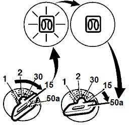
Speed selector
The Speed selector regulates the speed of the engine. In the ON LED Left position, the engine idles and in the ON LED Right position the engine runs at full speed.
Work/Transport mode
The 1st number buttonis used for work or transport mode selection Press the button to turn on the work mode with Red illumination in button and press again to turn On the transport mode.
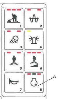
Emergency Stop
The Emergency stop button is used to stop the engine in an emergency situation which cannot be shut off in an usual manner. It switches off the engine and activates the brakes. The emergency stop aborts the entire control operation in a quicker way for the personnel safety.
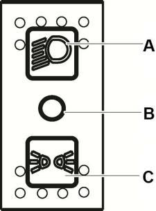
Sprinkler Switch
A. Sprinkler Manual/Auto
B. Sprinkler timer
5th Button for Sprinkler manual/auto mode selection, First press manual mode is activated with red illumination in Left side button. On second press auto mode is activated with red illumination in right side button, Machine running condition water flow comes on drum.
6th Button for sprinkler timer to adjust water spray in three mode.
A Emergency stop button
Forward/Reverse (FNR) Lever
The direction of travel and speed of the roller is regulated with the forward/reverse (FNR) lever. The roller speed increases or decreases in proportion to the lever position.
Seat Buzzer
The Seat buzzer beeps if the operator is not seated during the operation of the roller and it continues to beep until the operator sits on the seat. If the buzzer beeps for long the brakes are activated and engine is forced to stop.
Horn Button
The Horn button is located on the keypad button no 7
Press the button to activate the horn.
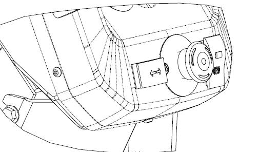
Drum Selector Switch
Depending on the Drum selector, the vibration is activated in the following places.
Left side button Activates vibration for front drum.
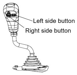
Right side button Activates vibration for rear drum.
Vibration High/Low Switch
In the one press, the High amplitude is activated with the red illumination in left side button.The function is activated with the switch. In the second press the Low amplitude is activated with Red illumination in right side button.
Fuse Box
Thefuse box is located on the control column that contains the fuses for the electrical system. Fuses protect the electrical components from short circuit damage. Refer to electrical system for the description and function of fuses.
Driving Lights Switch
Push Up position
Turns on driving lights.
Intermediate position Turns off all lights.
Depress position
Turns on parking lights.
A Push up position
B Intermediate position
C Depressed position
Working Light Switch
Depress the Working light switch to turn on the working lights.
Hazard Warning Lights Switch
The hazard warning lights are primarily used to warn other vehicles that there is a problem either with the roller, or there is a hazard in front of roller causing the operator to reduce the speed quickly.
Depress the switch to turn on the hazard warning lights.
Depress the switch to turn on the rotating beacon.
Direction Indicator Switch
The direction indicators are blinking lamps mounted near the left and right, front and rear corners of the roller. Depress the Direction indicator switch to either left or right to turn on the left or right indicators. In the intermediate position the function is shut off
Parking Brake On/Off Switch
The Parking brake On/Off switch is used to activate the parking brake.
N o t e Parking brake must be activated while starting the engine. Always activate the parking brake when the roller is stationary on a sloping surface.
Rotating Beacon Switch (Optional)
The rotating beacon lighting is generally used to warn the approaching vehicle of potential hazards, such as roller that is stopped or moving slower than the rate of the traffic.
Electrical control system
Functional Description – Display
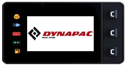
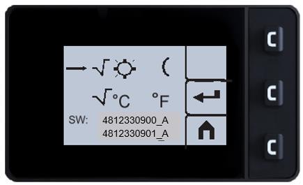
When the ignition key is activated to position 1, the start screen appears on the display (Fig. 1). This is shown for a two seconds and then switches over to the status screen.
Transport mode
The transport mode menu is shown when one of the three function keys to the right on the display is activated.
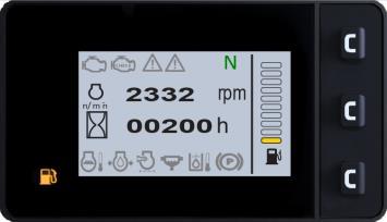
The status screening provides information about travel direction (2), Hour meter (3), fuel level (4) and Engine RPM (12).
Direction of work
The icon has three options (F, N, R) and is located in the top left corner of the Display (2).
➔ N (Neutral) – Indicates that the lever is in Neutral position.
➔ F (Forward) – A left arrow is shown in front of "F" on the display.
➔ R (Reverse) – A right arrow is shown after "R" on the display.
Hour meter
An icon (hour-glass) is shown on the left-hand side of the display for machine hours. The number of hours is shown to the right of the icon (3).
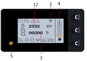
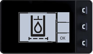
Fuel level
The fuel level is indicated as a no of lines of on the bar to the right of the display.
Once the first fuel bar is reached (bottom to top), it means the system has 10% of its total capacity, and the warning LED lights glow, indicating that you should refuel (5).
User settings
Users can change the lighting configurations (6), Brightness & contrast.
SW: - 4812330900 A– Display 4812330901_A – ECU software
Working mode – Vibration
Different Vibration modes are chosen by pressing the corresponding button (2) on the Keypad.
Vibration status
Vibration status activated on the drum (8).
Automatic Vibration Control – AVC
If AVC is activated from display selector switch, machine will runs with automatic vibration meaning that every time you don’t need to press vibration switch on FNR lever. Refer beside snap for this & follow below conditions.
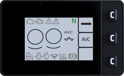
1) Select button of display in front of AVC=it will appear on display as shown in beside-encircled snap.
2) Activate work mode from Keypad.
3) Select either low or high amplitude from Keypad.
4) Switch 'ON' Vibration Sw.on FNR lever=only once.
5) Whenever machine comes in neutrl-vibration will stops & whenever it moves away from neutral=vibration will automatically starts .This time you dont need to select anything-thus its AVC.
Function Description
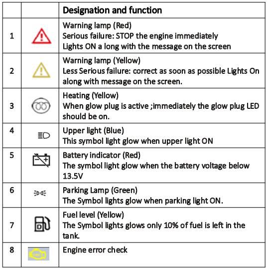
Control Panel Warnings Symbols
Warning lights turn on when the starter switch is turned to the on position and turn off when the engineis started. If the lights turn on even when the engine is running indicates a faulty condition.
Table 5-1:Warning Lights
Designation Function Description
Battery charging indicator.
When battery voltage is low i.e.<12.5V,the charging symbol should come with Orange red alert as per beside snap.
Diesel engine lubricating oil pressure indicator.
When engine oil press. Level is low; immediately symbol should come with RED colour alert.
Diesel engine Coolant temperature indicator.
When engine temp. high; immediately symbol should come with RED colour alert.
Low fuel level indicator.
The lamp illuminates if the oil level is low inthe fuel tank.
Hydraulic oil filter
When Hydraulic Oil filter clogged; immediately pop up symbol should come.
Control Panel Notification Symbols
Notifications are displayed when the starter switch is turned to the on position and notifies that corresponding systems are operating.
Table 5-2:Notification Lights
Designation Function Description
Parking brake indicator
The lamp illuminates when the parking brake is activated.
The fuel level gauge monitors the fuel level in the fuel tanks of the roller.
The fuel level gauge
1. Total 10Nos.lines are appearing for fuel level indication as full. It’s solid or dark when tank is full
2. It’s hollow or blank when tank is empty/less fuel.
Hour meter
Ensure hour meter should clocked every after 1 hour with change in hour digits.
Glow plug indicator
Glow Plug indicator illuminates momentarily (for approximately 5 seconds.) once ignition is switched on.
When glow plug is active ;immediately the glow plug LED should be on.
Air filter indicator
When Air filter clogged; immediately symbol should come with RED colour alert.
Hydraulic oil temperature indicator
The indicator illuminates when hydraulic oil temperature increases beyond 103 to 106 °C (217.4 to 222.8 °F). When this indicator illuminates, stop the engine and find the fault.