2 minute read
Section 3:Special Instructions

from Dynapac Vibratory rollers CC425 Engine KOEL-4R1190NA1 CEV Stage IV Operating & Maintenance Manual

3.1 Operational Limitations
Standard Lubricants and Other Recommended Oils and Fluids
Before leaving the factory, the systems and components are filled with the oils and fluids specified in the lubricant specification. These are suitable for:
• Ambient temperatures in the range of 4°C to +50°C (39.2°F to 122°F)
• Cold start in the range of 4°C to -15°C (39.2°F to 5°F)
Higher Ambient Temperatures
For operation of the roller at higher ambient temperatures, however maximum +50°C (122°F).
The diesel engine can be run at this temperature using normal oil.
Hydraulic system - mineral oil Dynapac Hydraulic 300 or similar.
Lower Ambient Temperature - Freeze Risk
Make sure that the watering system is empty/drained of water (sprinkler, hoses, tank/s) or that anti-freeze has been added, to prevent the system freezing.
Temperatures
The temperature limits apply to standard versions of rollers.
High Pressure Cleaning
Do not spray water directly onto electrical components or the instrument panels.
Place a plastic bag over the fuel filler cap and secure with a rubber band. This is to avoid high pressure water entering the vent hole in the filler cap. This could cause malfunctions, such as the blocking of filters.
Do not spray with high-pressure cleaner directly onto gaskets and bearing spacings in steering hitch.
Do not spray water directly onto electrical components or the instrument panels. Place a plastic bag over the fuel filler cap and secure with a rubber band. This is to avoid high pressure water entering the vent hole in the filler cap. This could cause malfunctions, such as the blocking of filters.
Ambient Temperature Range
The ambient temperature working range between limits of 4°C to +50°C (39.2°F to 122°F).
Operating Conditions For Stability
Stability is affected by the orientation of the roller, surface stability (bearing strength), and wind conditions.
Travel at a safe speed relevant to surrounding conditions.
Contact the local Dynapac distributor, dealer, or service office for further information.
N o t e Specifications represented are calculated values at 100% efficiency.
Operator life may be endangered if the following is not complied with. Do not add attachments to the roller that intrude into the operator protective area, reduce visibility, restrict emergency exits, or add weight exceeding certification weight. See the operation manual or contact the dealer for complete inspection requirements and maintenance instructions.
Grade Limitations
Exceeding the slope or grade limitations of the roller and its configuration can cause the roller to tip over. Prior to moving the roller into position, always determine the safe operating grade of the roller.
Fire Fighting
If the roller catches fire, use an ABC-class powder fire extinguisher.
A BE-class carbon dioxide fire extinguisher can also be used.
Battery Handling
When removing batteries, always disconnect the negative cable first.
When fitting batteries, always connect the positive cable first.
Dispose old batteries in an environmentally friendly way. Batteries contain toxic lead.
Do not use a quick-charger for charging the battery. This may shorten the battery life.
Fig. Ignition key & battery disconnector
1. Ignition key
2. Battery disconnector
Ignition key & Battery Dis-connector key removal In transit
While transporting the machine on the trailer or container or in long-term parking always ensure that
1. Ignition key should be removed from the Ignition switch
2. Battery dis-connector key should be removed
This will avoid static parasitic current consumption & saves the battery life & potential battery drain issue
Jump Starting
Do not connect the negative cable to thenegative terminal on the dead battery. Aspark can ignite the oxy-hydrogen gas formed around the battery.
Check the battery used for jump startinghas the same voltage as the dead battery.
1. Turn off the ignition and all power consuming equipment.
2. Switch off the engine on the roller which is providing jump start power.
3. Connect the jump start battery's positive terminal (A) to the flat battery's positive terminal(B).
4. Connect the jump start battery's negative terminal (C) to, for example, a bolt (D) or the lifting eye on the roller with the flat battery.
5. Start the engine on the power providing roller. Let it run for a while. Now try to start the other roller.
6. Disconnect the cables in the reverse order.
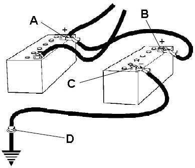
A Battery's positive terminal one
B Battery's positive terminal two
C Battery's negative terminal three
D Battery's negative terminal four