7 minute read
3.6 Lubrication and maintenance operations


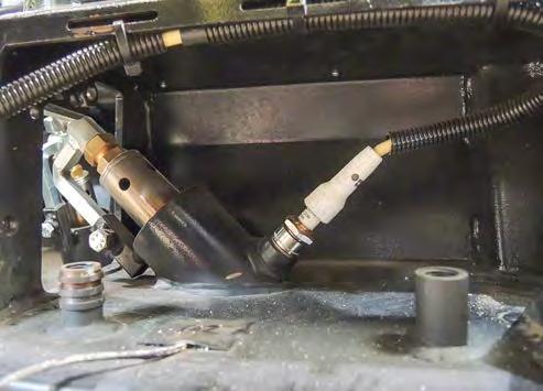
Spark plug check procedure:
• Dismount the cable (4) of a spark plug (3).
• Dismount the spark plug (3).
• Check the middle electrode (5)
• If the spark plug is too burned, replace the spark plug (3) for a new one.
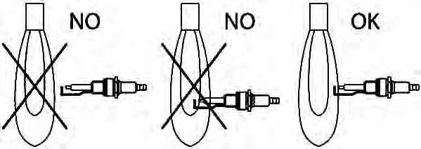
• Measure the distance between the middle electrode (5) and the external electrode (6). The correct distance must be 4 mm (0.2 in).
• In case of incorrect distance, adjust the distance between the middle electrode (5) and the external electrode (6) by slightly bending the external electrode (6).
• Screw in the spark plug (3).
• Mount the cable of the spark plug (4).
• Perform the spark plug test again according to the previous procedure.
• Unless the burners start within a few seconds, repeat the whole procedure. Perform maintenance of spark plugs when the machine is parked on a flat and solid surface with the engine and battery disconnecter off.
Have the test and maintenance of spark plugs performed by an authorised service plant or qualified personnel according to the given procedure. There is a risk of burns. Use protective equipment.
Gas flame position adjustment:
• Open the access to the burners.
• Insert the key into the ignition box (11) in the position “0” and switch over to the position “I”.
• Set the key between position “I” and “II” and the engine glowing indicator lamp (24) will light up.
• Do not perform engine glowing for more than 15 s.
• Use the alarm horn (12) to signal that the engine is starting.
• Turn the key to position “II” to start the engine.
• Secure the screed against free fall.
• Set the maximum paving width on both sides of the machine
• Turn the key in the ignition box (11) from position “II” to position “I”. The engine switches off.
• Turn the key in the ignition box (11) from position “I” to position “0” and disconnect the battery disconnecter.
Gas flame adjustment procedure:
• Have the correct position of the gas flame adjusted.
• Have the flame position adjustment performed by an authorised service plant or qualified personnel according to the procedure given below.
• Adjust the distance (D) between the gas burner (3) and the spark plug (4).
• Adjust the distance (D) by loosening the gas burner set screw (1) on the burner holder (2).
• The distance (D) can only be adjusted within the MIN and MAX marks. The values of MIN and MAX are marked on the burner holder (2) by marks.
• After adjusting the burner (3), tighten the burner set screw (1) on the burner holder (2).
• Test the ignition of the burners. In case of incorrect adjustment, repeat the gas flame adjustment procedure.
Perform gas flame adjustment when the machine is parked on a flat and solid surface with the engine and battery disconnecter off.
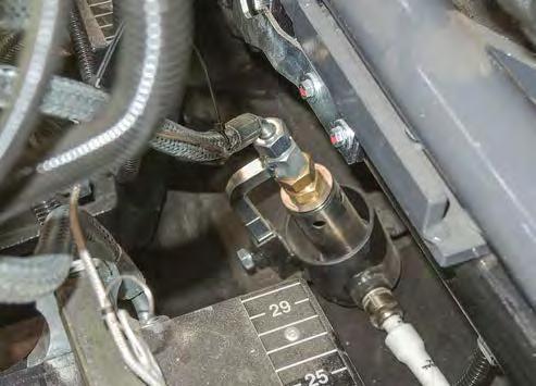
Have the gas flame adjustment performed by an authorised service plant or qualified personnel according to the given procedure.
There is a risk of burns. Use protective equipment. There is a risk of explosion.
Do not smoke during machine operation. There is a risk of explosion or fire. Liquid gas can easily ignite. The machine must be equipped with a fire extinguisher. Have the fire extinguisher ready on the driver's stand at a place intended for this purpose.
3.6 Lubrication and maintenance operations
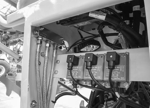
3.6.8 Gas equipment tightness check
Check the gas equipment for leakage when the machine is parked on a flat and solid surface and the valve (5) of the gas bottle is open.
Gas equipment tightness check procedure:
• Start the engine.
• Switch on the screed gas heating.
• Check the tightness of the gas equipment, e.g. with a gas leak detector.
• When checking the gas equipment, pay extra attention especially to any damage of hoses and potential gas leaks, and also check:
- All hoses (1)
- All fittings (2)
- Gas supply manifold (3)
- Gas supply solenoid valves (4)
- Gas bottle shut-off valve (5)
- Tightness of the reducing valve connection to the gas bottle (6)
- Pressure gauge (7)
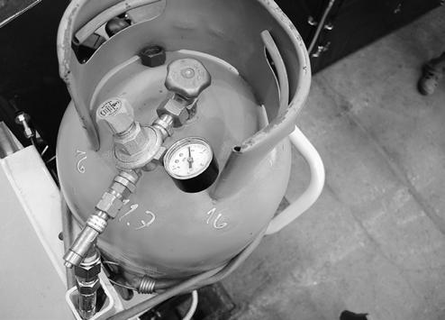
- Reducing valve (8)
- Safety valve (9)
- Tightness of the hose connection to the safety valve (10)
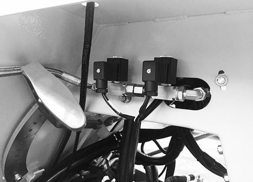
- Tightness of the hose and fitting connection to the burners (11)
• Test the gas equipment for leakage.
• In case of any leak, interrupt the gas supply and have the gas equipment repaired by an authorised service plant or qualified personnel.
• Close the gas bottle shut-off valve.
• Turn off the screed gas heating.
• Closed the gas supply.
• Stop the engine.
Do not smoke during machine operation. There is a risk of explosion or fire. Liquid gas can easily ignite.
The machine must be equipped with a fire extinguisher. Have the fire extinguisher ready on the driver's stand at a place intended for this purpose.
Pay extra attention to potential gas leaks and in doubt, shut off the gas supply.
Check the tightness of the gas equipment, e.g. with a gas leak detector.
If you detect gas leakage, immediately shut off the gas bottle shut-off valve and have the gas equipment repaired by an authorised service plant or qualified personnel.
Follow safety regulations for handling gas bottles. There is a risk of burns. Use protective equipment. Have the gas equipment tightness check performed by an authorised service plant or qualified personnel.
3.6.9 Brake test
3.6.9.1 Check of the parking brake
This test verifies the function of the parking brake. The operator must be present at the driver’s workplace – machine footboard – throughout the test. Perform the test on a slope with a gradient of 25% (14°). Stop the machine with a full hopper on a slope with the engine running.
Check that the area in front of and behind the machine is empty and that there are no persons or obstacles there! Ensure a suitable safe distance in front of the machine, behind the machine as well as on its sides.
Procedure
Fill the hopper of the paver (gravel or other loose materials, e.g. sand).
Start the engine according to Chapter 2.5.8.
Drive the machine onto a solid surface of an inclined plane (slope, ramp) with a slope of 25% (14°).
Stop the machine by changing the travel controller (8) to the neutral position “N”. The parking brake indicator lamp (23) lights up.
The machine must remain at standstill for ca. 5 min. The machine must not start to move. If the machine starts to move, the test is unsuccessful – apply the operating brake to drive the machine safely downhill.
After a failed brake test, secure the machine with wedges against unintentional movement on a horizontal surface and contact the service.
Note:
Have the parking brake checked by an authorized service centre every 1000 hours of operation.
3.6 Lubrication and maintenance operations
3.6.9.2 Check of the emergency brake
This test verifies the function of the emergency brake. Due to possible wear of the parking brake, the emergency brake check is to be performed with a stationary machine. During normal operation, the emergency brake button is to be used in the event of danger when the machine is running. After pressing the emergency brake button, the traction force immediately stops and the parking brake (P) engages.
Check that the area in front of and behind the machine is empty and that there are no persons or obstacles there! Ensure a suitable safe distance in front of the machine, behind the machine as well as on its sides.
Procedure
Place the machine on a flat and solid surface. Stand in the driver’s place and start the engine according to Chapter 2.5.8.
Set the travel controller (8) to the neutral position “N”. The parking brake indicator lamp (23) lights up. The machine is braked.
Press the emergency brake button (1). The engine of the machine stops and the “STOP” indicator light (26) lights up.
If the engine does not shut down, turn it off using the key in the ignition box, secure the machine against spontaneous movement using wedges on a level and solid surface and contact service.
Note:
The emergency stop button (6) is only to be used to stop the machine in an emergency. Use the service brake to stop the machine normally. To turn off the engine normally, use the ignition box (19) – turn the key to the “0” position.
3.6.9.3 Check of the service brake
This test verifies the function of the service brake. After activating the service brake, the hydraulic components of the machine drive adjust to stop the machine. The service brake can be controlled at any time. Using the service brake does not activate the parking brake (P).
Check that the area in front of and behind the machine is empty and that there are no persons or obstacles there! Ensure a suitable safe distance in front of the machine, behind the machine as well as on its sides.
Perform the test on a level and solid surface. If the test is performed on a slope, the machine may start moving due to leaking hydraulics even though the service brake is in order!
Procedure
Place the machine on a flat and solid surface.
The operator must be present at the driver’s workplace – machine footboard – throughout the test.
Set the machine in motion by setting the travel controller (8) to the forward travel position “F”.
Set the travel controller (8) almost to the neutral position “N”.
The machine will decelerate and the parking brake “P” will not be activated.
To set the machine in motion again or control the brake during the braking itself, move the travel controller (8) back to the forward travel position “F”.
If the machine does not decelerate, activate the emergency brake, secure the machine with wedges against unintentional movement on a horizontal surface and contact the service.
Activation of the emergency brake will cause a high mechanical and hydraulic load of the machine. Always test the parking brake after activating the emergency brake while driving.