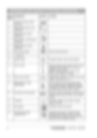
INSTRUMENTS AND CONTROLS, FUNCTIONAL DESCRIPTION Item in Designation fig. 4
Symbol
1
Direction indicator switch (Optional)
2
Working light switch, rear (Optional)
3
Hazard beacon switch (Optional)
4
Driving lights, On/Off switch (Optional)
5
Hazard flashers switch (Optional)
6
Horn (Push button)
7
- (Optional)
8
Starter button
Energizes starter motor while pressed.
9
Power switch
Electric starting circuit broken in the 0 mode. All electric instruments and controls are powered in the 1 mode. DEUTZ. The electric circuit may not be broken when engine is running.
10
Brake warning light
EMERGENCY BRAKE is applied when lamp I lights. Controlled via (11).
11
EMERGENCY STOP (Red button)
OFF (Pulled out) is normal setting when driving. ON (Pushed in) applies the brakes and stops the machine. After use, reset the forward/reverse control (24) to neutral.
Press to sound the horn.
STOP
8
Function
12
Oil pressure warning lamp
Stop the engine immediately if warning lamp LIGHTS and locate the cause. See, Engine Manual.
13
Voltmeter
Indicates voltage of the system. Normal range 12 to 15 V.
14
Fuel gauge
Indicates content of fuel tank.
15
Temperature gauge hydraulic fluid
Indicates temperature of hydraulic fluid. Normally 65°C to 80°C (150°F to 178°F). Stop the engine if gauge shows temperature above 85°C and locate the cause.
CA 251/301 O251EN2
