3 minute read
Opening of the Guards


The C Model
To ensure safety, the movable guards in the combine have been equipped with a locking device. They cannot be opened without the appropriate tool supplied with every combine, hanging on a hook on the back wall of the cab. (The guards can also be opened with a 13 mm socket wrench or a screwdriver.) The guards get locked automatically when closed. Some guards also have additional clamps.
Unlock the guard at the left end of the cutting table by turning the locking device counter-clockwise. To open the guard, pull the handle outwards and lift the guard slightly upwards at the same time. Fig. B1a.
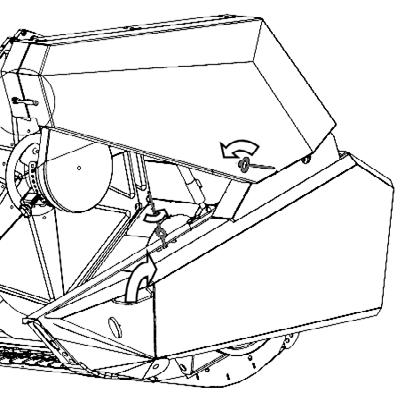
Unlock the belt drive guard on the reel by turning the locking device counter-clockwise. The rubber clamps need to be opened first. The guard is kept open by means of a gas spring. Fig. B1a.
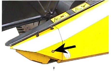
The side guards, fig. B2a, are released by placing the tool in the hole at the lower part of the guard and turning counter-clockwise. The guard opens when the lower edge is pulled outwards. The guard rests on the gas springs. The guard is locked automatically when closed. B1a

B2a
The L Model
To ensure safety, the movable guards in the combine have been equipped with a locking device. They cannot be opened without the appropriate tool supplied with every combine, hanging on a hook on the back wall of the cab. (The guards can also be opened with a 13 mm socket wrench or a screwdriver.) The guards get locked automatically when closed. Some guards also have additional clamps.
Unlock the guard at the left end of the cutting table, fig. B1b by turning the locking device counter-clock wise. To open the guard, pull the handle outwards and lift the guard slightly upwards at the same time. The guard gets locked automatically when closed. B1b
The side guards, fig. B2b, are released by placing the tool in the hole at the lower part of the guard and turning counter-clockwise. The guard opens when the lower edge is pulled outwards. The guard rests on the gas springs. The guard is locked automatically when closed.
Depending on the specification the lower guards on the combine may open. The front and rear of the guard can be opened separately. First open the top guard as instructed above. After that the front of the lower guard is opened by unlocking the front of the guard using the tool. Fig. B2c. To open the rear, release the catch at the rear of the guard. There is space for a tool kit on the left behind the front guard.
B2b

B2c
The rear guard of the chopper, fig. B3, (straw spreader) is released by opening the side locks on both sides of the combine. The guard gets locked in the upper position. When the guard is lowered, make sure the guard gets locked at the required height on both sides.
The locking on the rear door to the straw hood, fig. B3, is released by placing the tool in the hole at the lower part of the guard and turning counter-clockwise. The guard opens upwards and rests on the gas springs.

B3
The locking on the guard on the engine air intake is opened by placing the tool in the hole on the rear corner of the guard and turning counter-clockwise, fig. B4.
The top door to the straw walker compartment is locked with a hexagonal screw.

B4
Open the locking on the grain tank cover, fig. B5, by placing the tool in the hole and turning counterclockwise.
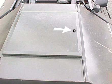
B5
Depending on the specification, there may be a cover above the engine compartment that can be opened. Open the cover like this: • Unlock the rear locks on both sides of the cover using a tool and turn the rear cover on top of the top cover. Fig. B6. • Push the top cover forward so that the rolls go all the way into the locking notch. The cover folds up from the middle.

B6