2 minute read
Fitting 3/ ORB - 1/ BSPP 1


5 - ASSEMBL Y
Front loader arm hydraulic system
Ride control
Boom hydraulic line removal
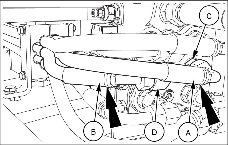
the main control valve, locate the hose (A) (marked with grey tie, see arrow) and the hose (B) (marked with brown tie, see arrow). Remove the hose (A) from the fitting (C) and the hose (B) from the ° elbow (D) . Remove the fitting (C) from the port A2 the main control valve and the ° elbow (D) from the port B2 the main control valve.
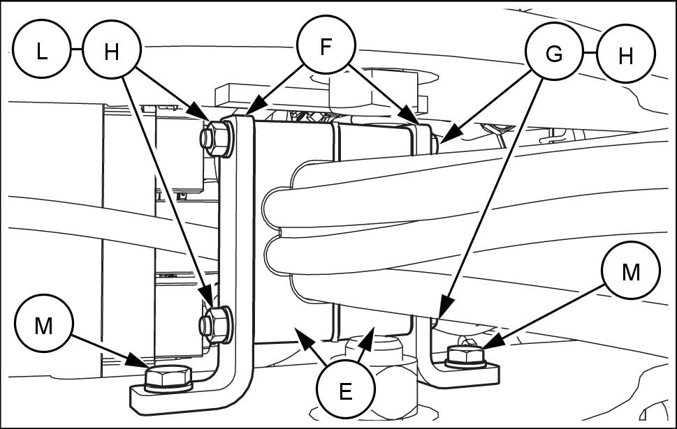
the rear frame, remove the bolts (G) , the washers (H) , and the nuts (L) separate the clamps (E) . Loosen the bolts (M) move the plates (F) and facilitate the removal the hose (A) and the hose (B) (see also Figure 1) from the clamps (E) .
LEIL19CWL0339AA 1
LEIL19CWL0341AA 2
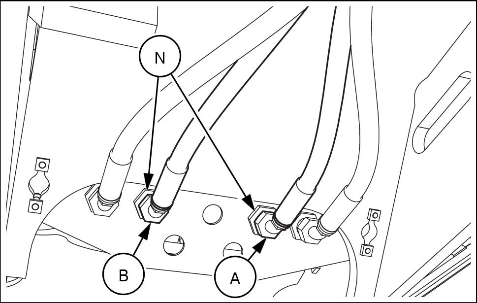
the front frame, remove the hose (A) and the hose (B) from the fittings (N) .
NOTE:
• See Figure 3 for configuration without anti - drop valves. • See Figure 4 for configuration with anti - drop valves.
Remove the hose (A) and the hose (B) from the machine.
Ride control valve assembly
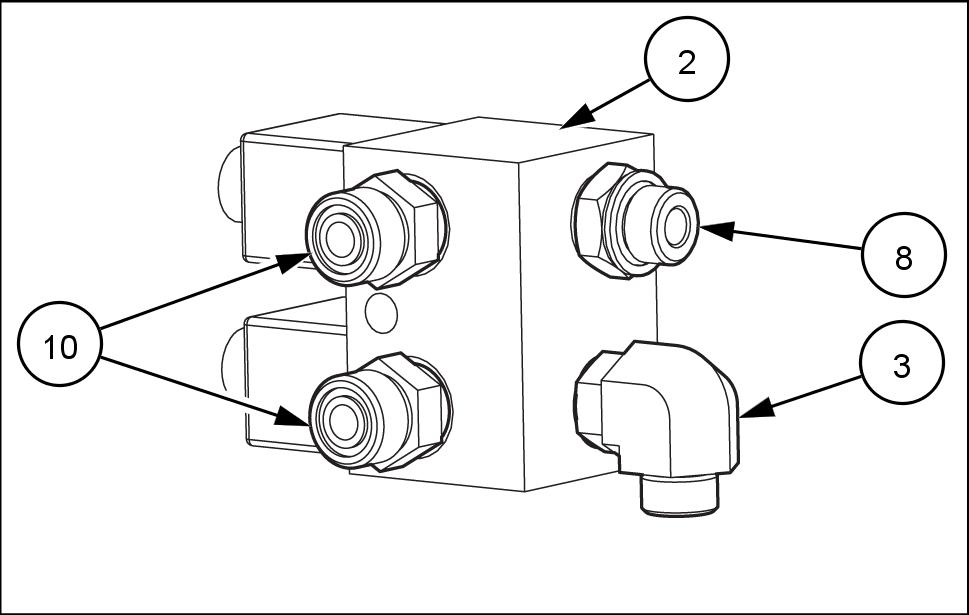
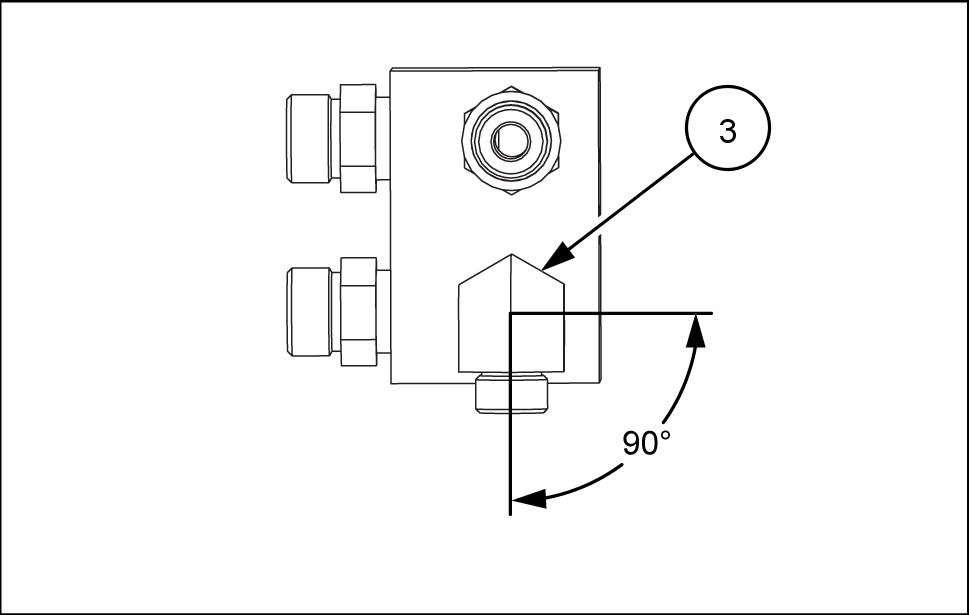
the ride control valve (2) , install the following fittings and ° elbow: • Port P1 – fitting (10) • Port P2 – fitting (10) • Port ACC – fitting (8) • Port T –° elbow (3) . Tighten the fittings (10) , the fitting (8) , and the ° elbow (3) N·m ( ). 10. Adjust the ° elbow (3) shown in Figure 6.

LEIL19CWL0349AA 3
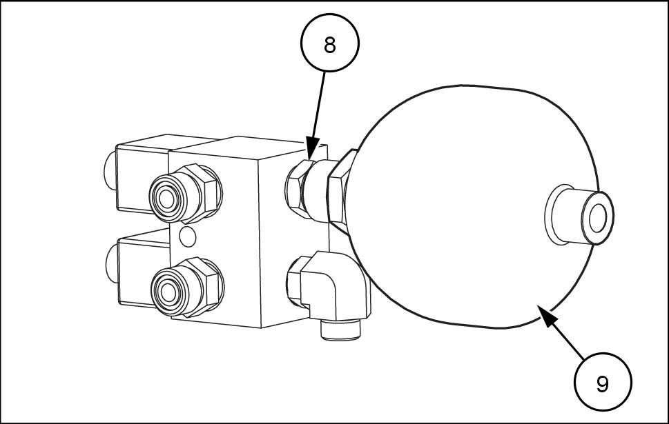
LEIL19CWL0372AA 4
LEIL19CWL0315AA 5
LEIL19CWL0314AA 6
1 Install the accumulator (9) the fitting (8) . Tighten 136 N·m ( 100 ).
Ride control valve installation
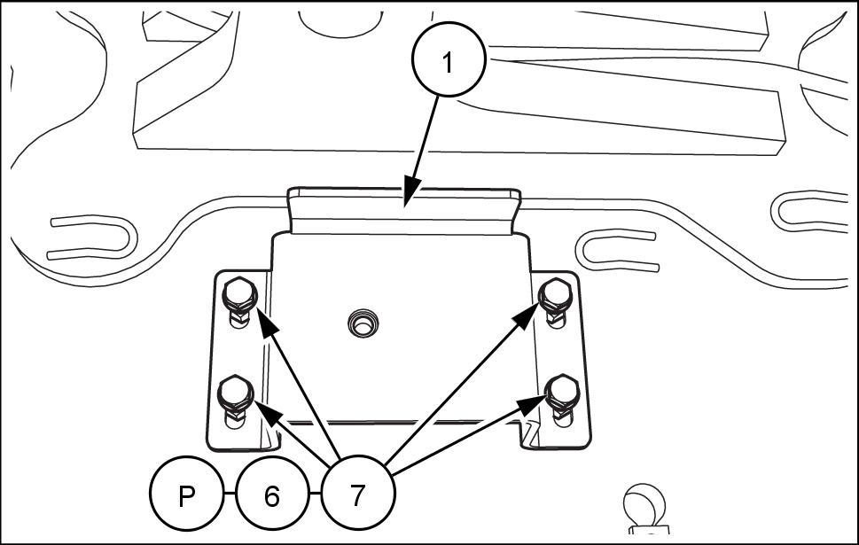
12. the left - hand side the rear frame, under the steering cylinder , locate the four welded nuts (P) . 13. Install the bracket (1) the rear frame. Use the bolts (7) , the washers (6) , and the nuts (P) .
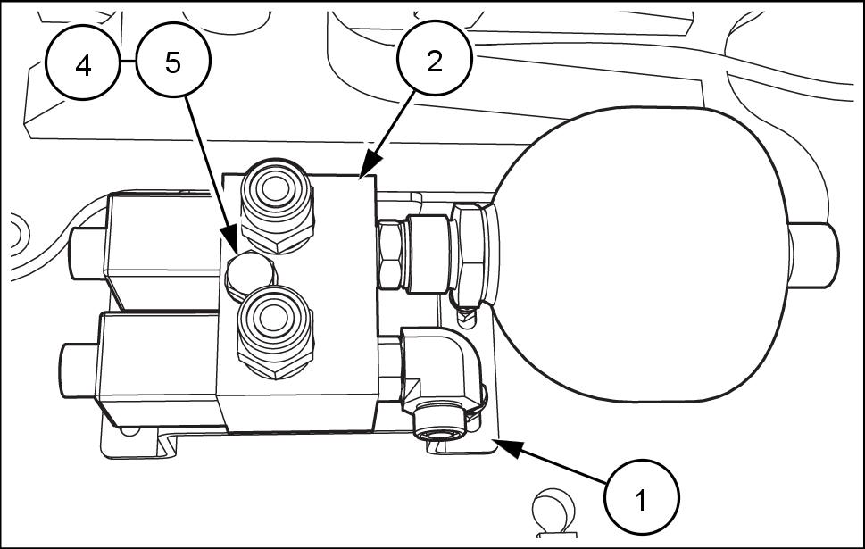
14. Install the ride control valve (2) assembly the bracket (1) . Use the bolt (5) and the washer (4) .
LEIL19CWL0316AA 7
LEIL19CWL0317AA 8
LEIL19CWL0318AA 9

