5 minute read
ASSEMBL Y

from CNH Object Handling kit 580ST 580T Loader backhoe Installation Instructions Manual 48161061 - PDF DO

2 - KIT CONTENT
Kit overview
Item Description Quantity Part Reference
1 V AL VE, LOCKING 2 47918221 2 HYDRAULIC HOSE 1 47546563 3 STRAIGHT FITTING 3 85802803 4 STRAIGHT FITTING 2 83963000 5 TUBE, RIGID, DIPPER 1 47900175 6 STRAIGHT FITTING 1 858051 7 TUBE, RIGID, BOOM 1 47898191 8 HYDRAULIC HOSE 2 85815505 9 CLAMP 4 214–1496 STRAIGHT FITTING 2 85805124 11 PRESSURE SWITCH 1 48019155 TIE STRAP 4 14560187 ELECTRIC HARNESS, CAB 1 84262837 SWITCH 1 227359A1 PLA 1 87704587 BUZZER 1 87704586 HOOK, ZND, BACKHOE 1 47935452 UNION 1 84431473 HYDRAULIC HOSE 1 47729308 TUBE, RIGID, BOOM 1 47926706 SP ACER 3 87303912 SP ACER 1 47601648 DECAL, LIFTING DIAGRAM 1 47896880 ELECTRIC HARNESS, BOOM 1 48092687 SEALING W ASHER 1 47490068 CABLE TIE 4 79072960 ELBOW , 1 48159755 INSTRUCTION, INST ALLA TION 1 48161061
3 - PRE-ASSEMBL Y
PREP ARING FOR ASSEMBL Y
Prepare for assembly
READ COMPLETE INSTRUCTION SHEET BEFORE INST ALLA TION THIS KIT
NOTICE: The terms right hand and left hand, when used in this instruction, indicate the right (2) and the left (1) sides the machine seen from operators seat. Front (3) and rear (4) are also shown.
Reference numbers and letters illustrations are the same reference numbers and letters in the instructions.
Special torque specifications are included in the instructions. torque specifications are not included in the instructions, use standard torque specifications. See your Service Manual Authorized Dealer if you need standard torque specifications.
Preparing for Kit Component Upgrade
Park the machine a level surface. Place some wedges under the wheels in order prevent the machine from moving. Lower the stabilizers the floor .
Completely extend the dipper and the boom. Lower the boom until the bucket is the floor . Stop the engine and apply the parking brake.
RAIL14TLB0434BA 1

RAIL14TLB0861BA 2
Disconnect the electric system taking the battery master switch (A) the OFF position. The battery master switch is in the battery compartment. When the battery master switch is in vertical position, the electric system is connected. When the battery master switch is tilted 45°, the electric system is disconnected.
For Mechanical control machines, move backhoe control levers in all directions release any hydraulic circuit pressure. For Pilot control machines, refer the following procedure. A. T urn the key the “ON” position and depress the
Pilot Control System switch located the pilot tower . Green light indicating engagement the
Pilot Control System must turn and remain on. B. Move the backhoe control levers in all directions release any hydraulic circuit pressure.
T urn the key “OFF” position.

RAIL14TLB0862BA 3
4 - ASSEMBL Y
Excavator and backhoe hydraulic controls
Installation the object handling kit
Mandatory Declaration Conformity updates
NOTE: Hydraulic fluid may released during this procedure, prepared direct fluid into a suitable container and dispose properly . NOTICE: A void contamination, clean all connections before disconnecting tubes, hoses, connectors. Cap plug all ports after disconnecting.
NOTICE: The Dealer the person who guarantees for the correct installation the “Object handling” assembly must certify the correct assembly the Manufacturer , in order ask for the update the EC Declaration Conformity .
Dipper cylinder locking valve install
Remove the two existing hoses from the dipper cylinder and discard.
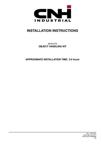
Assemble the locking valve (1) for the dipper cylinder installing the fittings in the valve ports follows:
Install the straight fitting (10) into the port “C2”.
Install the straight fitting (4) into port “V2”.
Install the straight fitting (3) into port “Pil”.
Install the locking valve (1) with its fittings onto the dipper cylinder . Connect the straight fitting (10) in port “C2” the existing fitting (E) the rod end the dipper cylinder .

RAIL16TLB0360AA 1

RAIL16TLB0350AA 2
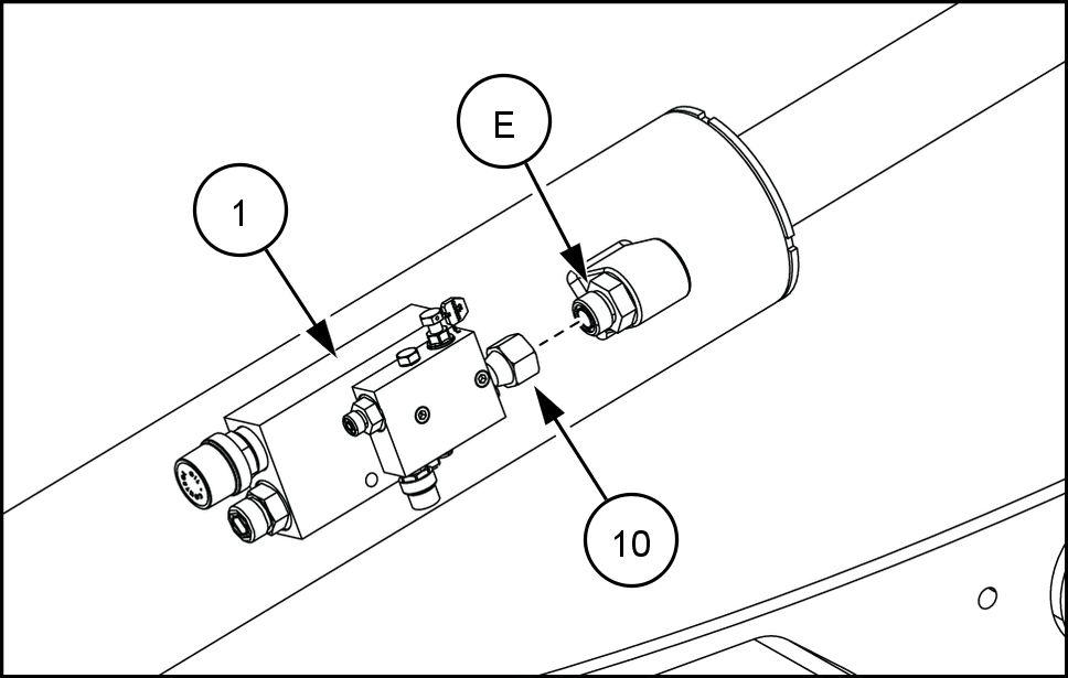
Connect the rigid dipper tube (5) the straight fitting (4) in port “V2”.
Connect the hydraulic hose (8) the straight fitting (3) in port “Pil”.
Secure the rigid dipper tube (5) the dipper cylinder with two spacers (21) and two clamps (9) shown.
Install the union (18) onto the rigid dipper tube (5) . Connect the hydraulic hose (2) the union (18) .
RAIL16TLB0345AA 4

RAIL16TLB0346AA 5

RAIL16TLB0347AA 6

RAIL16TLB0348AA 7
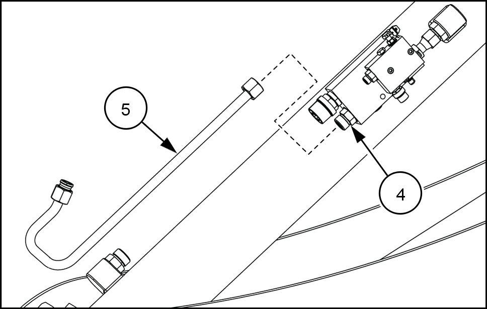
10. Install the straight fitting (6) onto the existing fitting (F) the base end the dipper cylinder . NOTE: Orient shown. 1 Install the straight fitting (3) onto the straight fitting (6) . 12. Connect the hydraulic hose (8) the straight fitting (3) . 13. Connect the hydraulic hose (19) the straight fitting (6) . 14. Connect the appropriate existing hydraulic hose install the machine the hydraulic hose (19) . 15. Connect the appropriate existing hydraulic hose install the machine the hydraulic hose (2) .
Boom cylinder locking valve install
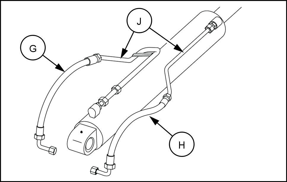
Disconnect the two existing hydraulic hoses (G) and (H) from the two existing rigid tubes (J) the boom cylinder . Remove the two rigid tubes (J) and discard.
Assemble the locking valve (1) for the boom cylinder installing the fittings in the valve ports follows:
Install the straight fitting (10) into the port “C2”.
Install the straight fitting (4) into port “V2”.
Install the straight fitting (3) into port “Pil”.
Install the locking valve (1) with its fittings onto the boom cylinder . Connect the straight fitting (10) in port “C2” the existing fitting (K) the rod end the boom cylinder .
RAIL16TLB0349AA 8
RAIL16TLB0364AA 9
RAIL16TLB0350AA 10

RAIL16TLB0351AA 11