4 - ASSEMBLY
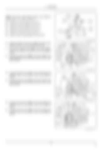
NOTE: The ports of the joystick control valve (5A) are marked with “I”, “K”, “MP”, “P” and “T”. 25. Install the connector (6) into the port “I”. 26. Install the connector (6) into the port “K”. 27. Install the connector (7) into the port “T”. 28. Install the connector (7) into the port “P”. 29. Install the quick coupler (8) into the port “MP”. RAIL16TLB1422AA
8
RAIL16TLB1435AA
9
30. Install the joystick control valve (5A) onto the support (G) with the M6 x 75 socket head screws (9). 31. Connect the straight end (10A) of the hose (10) to the connector (6) on the joystick control valve (5A) as shown. 32. Connect the bent end (10B) of the hose (10) to the elbow fitting (3) on the three spool loader control valve (1) as shown.
33. Connect the bent end (11A) of the hose (11) to the connector (6) on the joystick control valve (5A) as shown. 34. Connect the bent end (11B) of the hose (11) to the connector (4) on the three spool loader control valve (1) as shown.
RAIL16TLB1435AA
10
RAIL16TLB1423AA
11
35. Connect the bent end (12A) of the hose (12) to the connector (7) on the joystick control valve (5A) as shown. 36. Connect the bent end (13A) of the hose (13) to the connector (7) on the joystick control valve (5A) as shown.
12 EN


