1 minute read
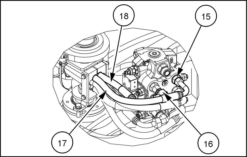
NOTE: apply the angle orientation the hoses (17) and 18) shown in figure

from CNH Hydraulic Standard Provision Kit 321F HS 321F STD W80C W80C HS Wheel Loader Instructions Manual

5 - ASSEMBL Y
Install
Hydraulic provision kit
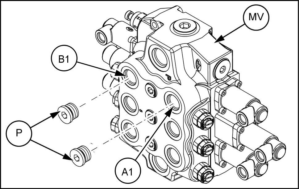
Unscrew and remove the two plugs (P) from the ports (A1) and (B1) the main control valve (MV) .
Discard the two plugs (P) . NOTE: during this operation, place a container under the main control valve (MV) prevent that the oil spills over the ground.
Install the two hydraulic connectors (15) the ports (A1) and (B1) the main control valve (MV) .
Install the ° elbow (16) the connector (15) located the port (B1) the main control valve (MV) .
Connect the hose (18) the elbow (16) . NOTE: the hose (18) has the yellow plastic tie both end.
Connect the hose (17) the hydraulic connector (15) located the port (A1) the main control valve (MV) . NOTE: the hose (17) has the orange plastic tie both end.
LEIL19CWL0162AB 1

LEIL19CWL0159FB 2
the rear chassis, locate the two mounting blocks (B2) and remove the plate (P1) the fixing hardware (see arrows). To facilitate the provision line hoses install, loosen the bolt (B1) .

LEIL19CWL0143AB 3
From the back side rear chassis, insert the two hoses (17) and (18) through the mounting blocks (B2) . NOTE: align the clamp side shown the figure 4 mark hoses (17) and (18) .
LEIL19CWL0161AB 4