1 minute read
Attaching the Mounting Frame ......................................... 6

from CLAAS DISCO 8550 C PLUS 8550 C DISCO 8550 PLUS 8550 DISCO 8550 C-T DISCO 8500 C Operator's Manual

7
4 1
5
9 8
6
8 29
30
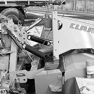
Mount one quick-release coupling to the available headstock of the adapter. Attach upper link (1) to the rear hole using the hitch pin (Fig.29). Attach the lower links (5) to the top hole of the quick-release coupling (6) and the rear hole (4) of the adapter (7) using the pins. If there should not be sufficient lifting height in the headland with a low cutting height, the lower links (5) should be attached to the front hole of the adapter (7). Attach the front mower (8) to the quick-release coupling (6) and secure in position. (Fig.29) Attach the universal shaft (9) to the main gearbox with the clutch end and then attach it to the front mower. Secure universal drive shaft gear against rotating by hanging in the chains. (Fig.30)
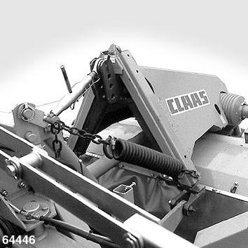
Note:
If you are using the mower as shunted combination, you will require propeller shaft M04 0160 (0937 043.3) for the front mower!
M04 0160 937 043.3
64531F