2 minute read
Rotation monitoring .......................................................... 7

from Claas DISCO 8700 C Plus DISCO 8700 C JAGUAR 8700 / 900 - 820 MODEL 492 / 491 Operator’s Manual - PDF

67675
7
47
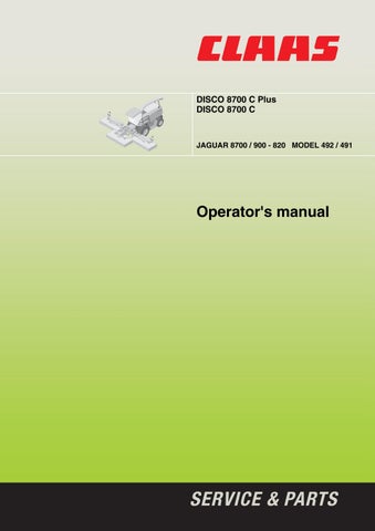
7.When driving on the roads, hitch the safety chain(7) on to the side mower units. The safety chain(7) serves simultaneously as a restraint for the side mower units (Fig.47). 8.Check the mower unit for roadworthiness and operational safety.
Caution!
Maintain a sufficient distance between the middle mower unit and the windscreen of the cab. Maintain a sufficient distance between the mower unit and the ground. Ensure adequate vision when driving. If the field of vision is restricted by the mower unit, a person to direct at road crossings and openings will be required.
Driving on public roads
When driving on public roads, observe the relevant road traffic regulations. Do not exceed the technically permissible axle loads and total weight. If the distance between the rear edge of the harvester's steered wheel and the front edge of the mower unit is more than 3.5 m, the restrictions in field of vision which arise when exiting yards, or at road crossings and openings, must be compensated, if need be, by suitable operational measures such as someone to direct.
Side lights / warning signs
Side lights and warning signs must be attached facing forwards in accordance with regulations.
Adaptations to the forage harvester
For further information: –see »Additional weights« on page6.2 and »Lighting«, page6.3.
H

67294
S
67298
T

66 48
67
T
66
H
49 48
49 Reinstating JAGUAR900/890/870/850/830
(In this section, the item numbers in the pictures refer to the parts list in the fitting instructions.) Unscrew the hydraulic hoses(H), (48) and(67) from the right-hand lifting cylinder(66). Unscrew the T-piece(T) for fitting to the old hydraulic cylinder. Close off the feed line(48) to the pressure switch. Remove the right-hand hydraulic cylinder(66). Fit the old hydraulic cylinder on the right and connect. (Fig.48)
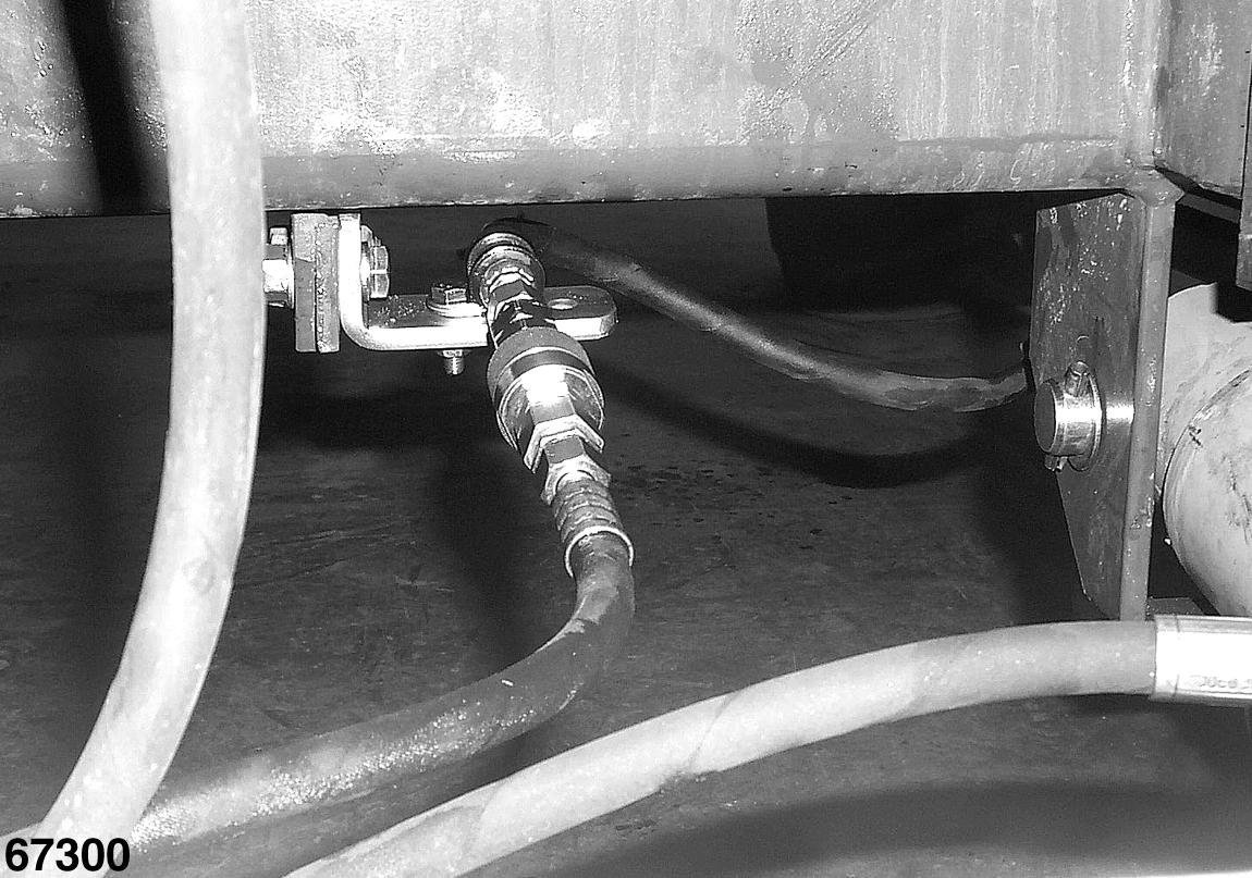
Unscrew hoses(S) and(H) from the left-hand hydraulic cylinder and remove T-piece (T) for use on the old hydraulic cylinder. Remove the left-hand hydraulic cylinder(66). Fit the old hydraulic cylinder on the left and connect. (Fig.49)
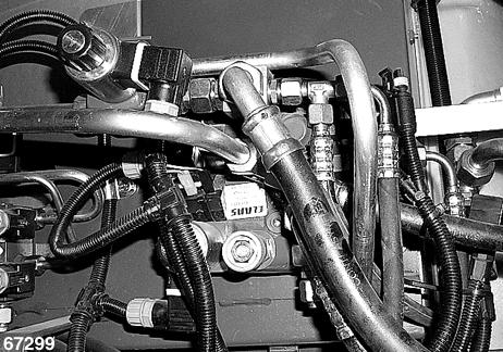
The tank return line(49) can remain on the valve block under the left-hand side cladding. (Fig.50)
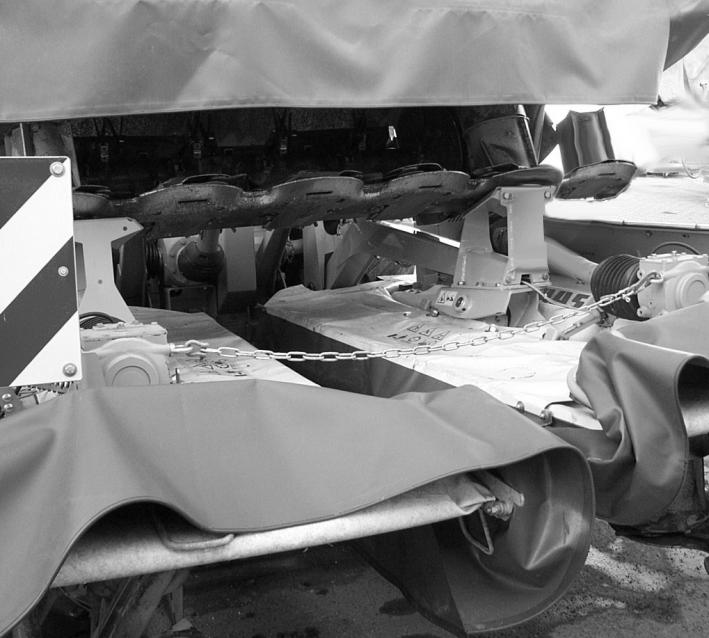
Separate the hydraulic line(H) from the mower unit, from the tank return line(49). Close off the tank return line. (Fig.51)
67299
H
49
67300