1 minute read
ADJUSTING THE CONTROL LEVER


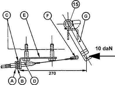
– Maintain the pin (15) and the cam in braking position. – Release the rod (G) by disconnecting the control cable (F). – Apply a force of 10 daN with a weight indicator connected to the rod end and position it so as to obtain a dimension of 270 mm between the cable attachment (E) and the rod axis. Remove and install successively the rod to obtain a dimension of 270 mm. – Connect the control cable (F). – Tighten the locknut (A) on the washer (B).
Note: For a good aligning of the sheath stop (D) and the cable (F), the nut (C) and the locknut (A) must be mounted at the front of the attachment bracket (E).
– Check operation of the control. – Tighten the lever, the braking initial stroke should be around 8 notches. The instrument panel indicator must light first in handbrake locked position. – Release the lever, the control must return freely to the idle position. In this position, the indicator must switch off.
362msm49 Fig. 14
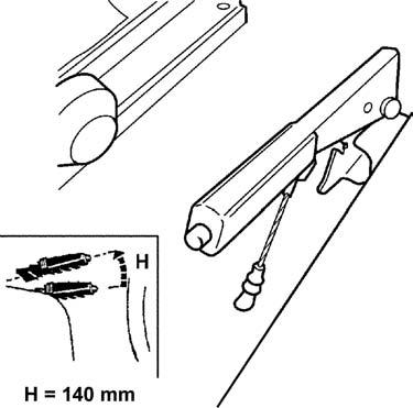
362msm51 Fig. 15