1 minute read
15.11 Key switch
CONTROL FUNCTIONALITY DESCRIPTION
Buttons for lifting and lowering initial lift (optional) Optional for stackers.
Switch for auxiliary device (optional) Optional for stackers.
Warning light for side stabilizers (optional) Optional for stackers. The warning light is turned on when the side stabilizers are lowered. The warning light is turned off when the side stabilizers are lifted back up.
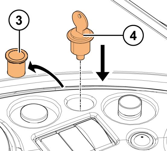
Figure 149. Key switch overview
The key switch option replaces the Start button in the control panel and removes the need for a PIN query.
The key switch switches the truck's electrical system on and off.
When the key switch is in the off position, the truck’s electrical system is turned off. Note however that power may be still connected to certain electronic devices.
Type
Contact rating
Electrical wiring
Switching output Key switch
24 Vdc / 6 A
Quick connect terminals 2.8 x 0.8 mm
2 x NC + 2 x NO, momentary action
Copyright© 2013 by MCFE. All rights reserved. Revision: A Document ID: 619098 312 (342)
15.11.1 Installation of the key switch
1. Open the control panel. For instructions, see section 5.4.2.
2. Remove the Start button and its contact block from the control panel. 3. Install the key switch and its contact block into the control panel.
4. Connect the key switch wires according to the truck model specific schematic diagram. 5. Set the parameter PIN CODE to OFF.

15.11.2 Key switch functionality check
Measure at the resistance area that the contacts inside the switch are not stuck together.
When the key switch is turned to the 0 position, the contacts are closed between pins 21-22 and 31-32 and the resistance is ~0 Ω. The contacts are open between pins 13-14 and 43-44 and the resistance is ~∞Ω.
When the key switch is turned to the 1 position, the resistance values are reversed.
If the contacts are stuck together or broken, replace the key switch.
Copyright© 2013 by MCFE. All rights reserved. Revision: A Document ID: 619098 313 (342)


