4 minute read
max.time belly
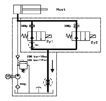
5.1.1.3. Fast mast lowering
Figure 5.11. Hydraulic fluid flow during fast lowering
1. The operator also activates the second tiller switch for lowering.The pressurised hydraulic fluid flows from the mast cylinders through two strainers.
2. The fluid flows through the magnetic valves (2Y1 and 2Y2).
3. The fluid flows through the flow restrictor back to the tank.
122
5.1.2. Hydraulic system of trucks with initial lift (1,200 kg capacity models)
NOTE
Make sure that you have the appropriate maintenance instructions and the schematic diagram for the truck model under maintenance.

Figure 5.12. Hydraulic system, 1,200 kg capacity trucks with initial lift (TH70 0105)
Figure 5.13. Hydraulic fluid tank with a strainer and filling cap
123
Figure 5.14. Return line with restricted flow
Figure 5.15. Main hydraulic pump and motor
Figure 5.16. Check valve for lifting and adjustable relief valve for the complete hydraulic system.The pressure adjustment depends on the mast type.
Figure 5.17. Lowering magnetic valves 2Y1 for slow lowering, with a restrictor below, and 2Y2 for fast lowering. Strainers on top of the valves keep dirt out of the system.

124
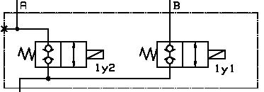
Figure 5.18. Locking valves 1Y2 for lifting and lowering and 1Y1 for initial lifting and lowering
Figure 5.19.Velocity fuses in lift cylinders.The position of the components depends on the mast construction, and is not shown in the hydraulic schematic diagram.
Figure 5.20. Mast.The actual mast may have more than one cylinder.
Figure 5.21. Initial lift cylinder

125
5.1.2.1. Mast lifting
The hydraulic schematic diagram in this section illustrates the operation of the hydraulic system in 1,200 kg capacity trucks with the initial lift.
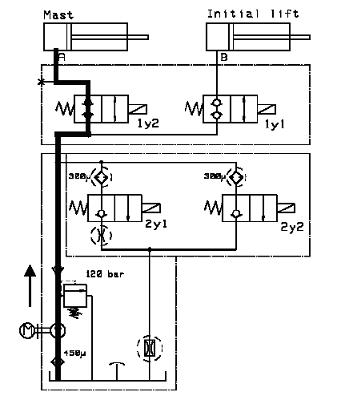
Figure 5.22. Hydraulic fluid flow during mast lifting
1. The operator activates the tiller switch for lifting.The motor starts the pump and the pump draws hydraulic fluid from the tank.
2. The hydraulic fluid is pressurised.
3. The pressurised hydraulic fluid flows to the relief valve and through the check valve to the locking valve (1Y2) and then to the mast cylinder.
126
5.1.2.2. Slow mast lowering
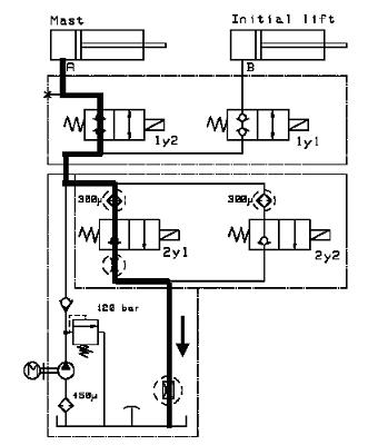
Figure 5.23. Hydraulic fluid flow during slow mast lowering
1. The operator activates the first tiller switch for slow lowering.
First the pressurised hydraulic fluid flows from the mast cylinders through the locking valve (1Y2) and then through the strainer.
2. The fluid flows through the first magnetic valve (2Y1).
3. The fluid flows through the flow restrictor back to the tank.
127
5.1.2.3. Fast mast lowering
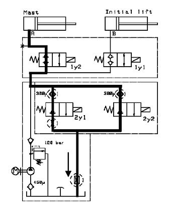
Figure 5.24. Hydraulic fluid flow during fast mast lowering
1. The operator also activates the second tiller switch for lowering.The pressurised hydraulic fluid flows from the mast cylinders through two strainers.
2. The fluid flows through the magnetic valves (2Y1 and 2Y2).
3. The fluid flows through the flow restrictor back to the tank.
128
5.1.2.4. Initial lifting
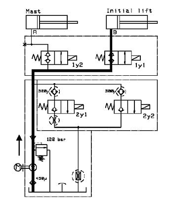
Figure 5.25. Hydraulic fluid flow during initial lifting
1. The operator activates the tiller switch for initial lifting.The motor starts the pump and the pump draws hydraulic fluid from the tank.
2. The hydraulic fluid is pressurised.
3. The pressurised hydraulic fluid flows to the relief valve and through the check valve to the locking valve (1Y1) and then to the initial lifting cylinder.
129
5.1.2.5. Initial lowering

Figure 5.26. Hydraulic fluid flow during initial lowering
1. The operator activates the tiller switch for initial lowering.
First the pressurised hydraulic fluid flows from the initial cylinder through the locking valve (1Y1) and then through the strainer.
2. The fluid flows through the first magnetic valve (2Y1).
3. The fluid flows through the flow restrictor back to the tank.
130
5.1.3. Hydraulic system of trucks with HCU without initial lift (1,200 and 1,600 kg capacity models)
NOTE
Make sure that you have the appropriate maintenance instructions and the schematic diagram for the truck model under maintenance.
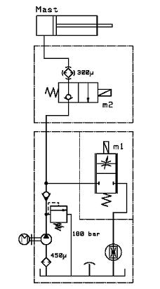
Figure 5.27. Hydraulic system, 1,200 and 1,600 kg capacity trucks with HCU without initial lift (TH71 0105)
Figure 5.28. Hydraulic fluid tank with a strainer and filling cap
131
Figure 5.29. Return line with restricted flow
Figure 5.30. Main hydraulic pump and motor
Figure 5.31. Check valve for lifting and adjustable relief valve for the complete hydraulic system.The pressure adjustment depends on the mast type.
Figure 5.32. Proportional valve M1 for lifting and lowering
Figure 5.33. Magnetic valve M2 for lifting and lowering
132


