8 minute read
dec. belly.tiller
5.1.4.4. Initial lowering
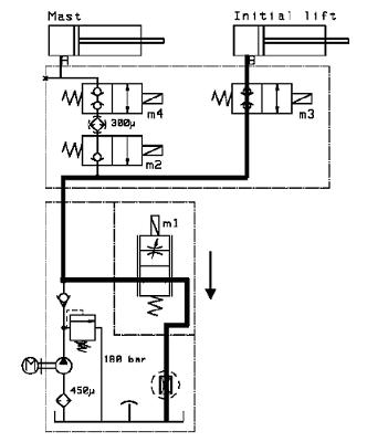
Figure 5.52. Hydraulic fluid flow during initial lowering
1. The operator presses the initial lowering button.The proportional valve (M1) is closed and M3 is opened.
2. The proportional valve (M1) opens to a predetermined value.
3. The fluid flows through the flow restrictor back to the tank.
5.2. Hydraulic maintenance and repairs
The following sections illustrate various hydraulic maintenance procedures not covered in Chapter 3 Regular maintenance.
5.2.1. Replacing gaskets
NOTE
When the gasket of the hydraulic cylinder needs to be replaced, the wiper and guide strips are also replaced.
To replace gaskets:
1. Pull out the piston rod from the cylinder.
142
NOTE
NOTE
2. Remove the wiper from the cylinder using suitable pliers.
3. Pull the old gasket carefully out of the cylinder. Do not use sharp tools.
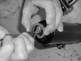
4. Squeeze the new gasket using round pointed pliers.The groove in the gasket goes inside the cylinder (towards the bottom of the cylinder). Do not scratch the inside walls of the cylinder.

Figure 5.53. Squeezing the gasket
5. Attach the new wiper to the cylinder.The wiper prevents dirt from entering the cylinder when the piston rod moves.
6. Insert the piston rod into the cylinder.
5.2.2. Replacing the hydraulic pump
The hydraulic pump and tank assembly is located in the middle of the main chassis when viewed from the front.
To replace the hydraulic pump:
1. Remove the main and top covers of the truck.
143
2. The hydraulic pump and tank assembly is fixed to a bracket, which is fixed to the main chassis. Locate the bolts that fix the bracket to the chassis and open them.
The hydraulic pump and tank assembly is located in the main chassis with the tank at the bottom and the pump and motor above it. Open the filling cap. Use a draining apparatus to drain the used fluid from the tank. Ensure that all the tools and tubing you use are clean.
3. After opening the bolts, turn the assembly out of the chassis to gain access to it.
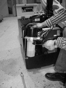
4. Open the four screws that hold the entire assembly together using a 4 mm Allen key. Be careful when handling the assembly with the screws removed.

Figure 5.54. Removing the hydraulic tank (1,600 kg capacity truck model)
5. Carefully remove the tank and drain out the old hydraulic fluid.
144
6. Detach the hydraulic hoses from the hydraulic pump and tank assembly.
7. Disconnect the electrical connections from the hydraulic pump motor.
8. Replace the hydraulic pump motor.
9. Connect the electrical connections to the new hydraulic pump motor.
10.Connect the hydraulic hoses to the hydraulic pump.
11.Attach the hydraulic tank to the hydraulic pump and fasten the four fixing screws.
12.Reattach the entire assembly to the main chassis.
13.After the tank has been drained, fill it with new hydraulic fluid to three-quarters of its capacity. Do not overfill. Be careful to avoid splashing the hydraulic fluid onto truck components.
Immediately wipe away any splashes. Close the cap, but be careful not to overtighten it.
145
6. Mechanical maintenance
This chapter presents the mechanical maintenance procedures not covered in Chapter 3 Regular maintenance. Refer to Section 3.1 Safety guidelines and preparation and Section 3.2 Maintenance guidelines for information on safety and preparation for maintenance tasks. Refer to Chapter 2 Operating the truck for operating instructions.
6.1. Replacing wheels
A truck has three wheel types: drive, load and castor wheels. Check all the wheels on a truck for damage and wear.The wheels should wear evenly and there should be no flats or holes in the wear surface.The wheels should also turn smoothly on their axles and there should not be play in the bearings. Even wear can be checked by driving the truck on a smooth surface to test that all the wheels turn and the truck rides smoothly. If a wheel or a bearing has sustained damage that affects use or if its surface has worn completely, it should be replaced.
To replace a truck wheel, follow the instructions given below. Never work under the truck if it is supported only by a jack.
WARNING!
6.1.1. Replacing the drive wheel
The drive wheel is located immediately under the tiller arm anchoring point and supports a considerable portion of the truck’s weight.The drive wheel is used to propel and steer the truck. It is attached to the drive motor via the transmission.The tiller arm is used to turn the drive wheel when steering the truck.
To replace the drive wheel:
1. Open the truck's main cover by unscrewing the two fixing screws.
2. Turn the drive wheel using the tiller arm so that the fixing screws of the wheel can be reached.
3. On 1,600 kg capacity trucks, remove the five wheel fixing screws with a 19 mm wrench. On 1,000 and 1,200 kg capacity trucks, remove the ten wheel fixing screws with a
147
5 mm Allen key. Do not remove the two countersunk screws, as they hold the planet gear rim in place.
4. Lift the truck from under the chassis using a suitable jack so that the drive wheel is lifted off the supporting surface.
5. Remove the old drive wheel.

Figure 6.1. Drive wheel of a 1,600 kg capacity truck
6. Attach the new drive wheel.
7. Replace the main cover and test the operation of the drive unit.
6.1.2. Replacing the load wheels
The load wheels are located near the ends of the forks.Their main purpose is to support the weight of the load. Depending on the truck model, there is either a single or a double load wheel in each fork.
To replace single load wheels:
1. Loosen the locking pin from the axle using a 5 mm pin punch.
The locking pin is located on the outside end of the axle.
148
2. Raise the forks and lift the truck slightly with a jack.
3. Remove the locking pin from the axle.
4. Remove the load wheel axle.
5. Replace the load wheel and reattach the axle and the locking pin.
To replace double load wheels:
1. Lift the truck using a jack. Place supporting brackets under the truck.
2. Remove the axle bolt using a 8 mm Allen key on both ends of the bolt.
3. Replace the load wheel and reattach the axle bolt.
6.1.3. Replacing the castor wheel
The supporting castor wheel is located under the main chassis opposite to the drive wheel.The castor wheel balances the truck and turns automatically to follow the direction of travel.
To replace the castor wheel:
1. Lift the truck using a jack. Place supporting brackets under the truck.
2. Remove the axle bolt using a wrench on both ends of the bolt.
3. Replace the castor wheel and reattach the axle bolt.
6.2. Replacing the tiller arm gas spring
This section gives instructions on how to replace the gas spring of the tiller arm.The purpose of the gas spring is to return the tiller arm automatically to the upright resting position. It is a safety device, which must always be fully operational.
To replace the gas spring:
1. Remove the cover from the base of the tiller arm.
149
2. Remove the ball joints from both ends of the gas spring using a 13 mm wrench.
3. Replace the gas spring.
4. Attach the ball joints to the tiller arm.
5. Reattach the cover to the base of the tiller arm.
6. Test the operation of the tiller arm.
Figure 6.2. Replacing the tiller arm gas spring
6.3. Lever system maintenance
The lever system is present only on trucks with initial lifting functionality.The system is composed of levers and the initial lifting cylinder between the main chassis and the mast assembly, and push rods under the forks.They operate to lift the mast and fork assembly evenly when initial lifting is used.The following procedures provide instructions for disassembling the system for maintenance purposes.
150

Figure 6.3. Lever system
The bushings in the initial lifting levers must be changed when play has developed in the system. WARNING! These procedures require the truck to be lifted and supported.Take care to support the weight of the truck and the separated components.Take care especially when removing the levers between the main chassis and the mast assembly.
To remove the pushrods:
1. Lift the truck.
2. Remove the locking pins from both ends of the push rods using a 5 mm punch.
3. Remove the shafts from both ends of the push rods. The shafts at the cylinder ends of the push rods cannot be removed by hitting them with a punch.You have to
NOTE
use an inertia hammer to pull the shaft out from the push rod.
4. Remove the push rods.
To remove the wheel forks:
1. Remove the load wheels from the wheel forks.
2. Remove the locking pins and detach the wheel forks.
To remove the hydraulic cylinder lever:
151
1. Remove the push rods.
2. Remove the circlips from the cylinder axle ends.
3. Remove the axle from the cylinder.There are two washers on each side of the cylinder attachment point.
4. Remove the lever.
To remove the upper and lower levers:
1. Remove the locking pins with a 4 mm punch.
2. Remove the axles. Depending on the lever end, gently hammer the axles out or remove them with an extractor.
3. Remove the bushings from the axle and install new ones.
152


