1 minute read
reverse braking
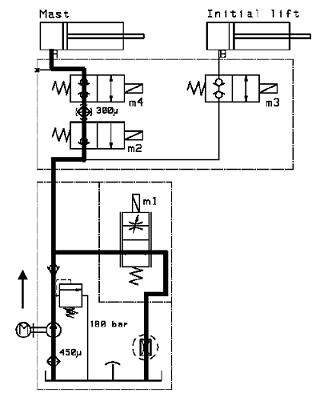
Figure 5.49. Hydraulic fluid flow during mast lifting
1. The operator moves the lifting/lowering control to the lifting position.The motor starts the pump and the pump draws hydraulic fluid from the tank.
2. The pressurised hydraulic fluid flows to the relief valve and through the check valve to the proportional valve (M1) and back to the tank.
3. The proportional valve (M1) is fully open.Then the valve is slightly closed and the pressure increases.This allows stepless control of lifting with loaded forks.
4. The pressurised hydraulic fluid opens the next check valve in M2.The locking valve (M4) is opened and the hydraulic fluid flows to the mast cylinder.
139
5.1.4.2. Mast lowering

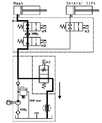
Figure 5.50. Hydraulic fluid flow during mast lowering
1. The operator moves the lifting/lowering control to the lowering position.The proportional valve (M1) is closed.The magnetic valve (M2) and the locking valve (M4) are opened.
2. The proportional valve (M1) starts to open slowly.This allows stepless control of lowering.
3. The hydraulic fluid flows through the flow restrictor back to the tank.
140
5.1.4.3. Initial lifting

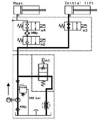
Figure 5.51. Hydraulic fluid flow during initial lifting
1. The operator presses the initial lifting button.The motor starts the pump and the pump draws hydraulic fluid from the tank.
2. The hydraulic fluid is pressurised.
3. The pressurised hydraulic fluid flows to the relief valve and through the check valve to the proportional valve (M1) and back to the tank.
4. The proportional valve (M1) is fully open.Then the valve is slightly closed and the locking valve (M3) is opened.This allows stepless control of lifting.
5. The pressurised hydraulic fluid flows to the initial lifting cylinder.
141


