
5 minute read
Appendix


208-0432 TERMINATION RESISTOR
6-pin Termination Resistor
• Used to terminate the ends of a data link run . Two termination resistors required .
• Used to connect 225-6107 tee to tee cables .
221-9506 TEE CONNECTOR
225-6107 TEE TO TEE CABLE
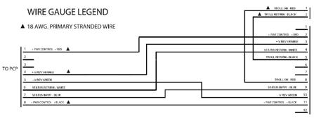
337-0962 FOR MSCS II SYSTEM
225-6102 CUSTOM PANEL HARNESS
• Port or starboard J1939 tee to tee connections . • J1939 data link connection from ECU to tee connector at ETP . • Tee to tee connections on the control station data link when there are two or more control stations on the data link . • Tee to tee connections on the backup control station data link when there are two or more backup control stations on the data link . • Port or starboard ECU J1939 connector (termination resistor) to ETP tee connector .
• Connects the custom panel into the MJB .
225-6112 MPD DROP HARNESS
337-0959 & 337-0958 FOR MSCS II SYSTEM
• Connects MPD display into the J1939 datalink . • Requires 221-9506 tee connector .
225-6116 TRUNK HARNESS
• Connects the MJB to the ECU 70-pin connector .
225-6118 CDL INTERFACE CONNECTOR
226-0361 KEYSWITCH ALARM HARNESS
• Provides + and - battery and CDL + and CDL - to the helm station . • Used to connect Engine Vision, EMS, or Cat ET into the Caterpillar electronic system .
• Connects 217-3865 keyswitch panel to the MJB .
226-0363 CONTROL STATION HARNESS
337-0964 FOR MSCS II SYSTEM
• Connects the master control station to the PCP . • Connects a single control station to the control station data link . • Connects a single backup control station to the backup control station data link . • Termination resistors are not required .
226-0365 PCP STATION DROP
• Connects the PCP into the control station data link and/or the backup control station data link when there are two or more control stations on the data link .
226-0366 CONTROL STATION DROP HARNESS
BACKUP CONTROL STATION DROP HARNESS
1 2 3 4 5 6 1 2
12 11 10 9 8 7 6 5 4 3 2 1
• Used to connect the control stations into the control station data link when there are two or more control stations on the data link . • Used to connect the backup control stations into the backup control station data link when there are two or more control stations on the data link .
226-0367 THROTTLE/J1939 HARNESS
• Connects the PCP into the J1939 data link . • Connects the throttle signal to the MJB where it is then routed to the ECUs .
226-0369 PCP POWER SUPPLY CABLE
• Routes the battery connections from the MJB to the PCP .
Note: Special attention should be given to the power connector orientation when plugging the power cable into the PCP and MJB. The power connector is keyed, but can be inserted into the connector upside down.
226-0371 TRANSMISSION HARNESS
REVISION -02
REVISION -03
311-8401 TRANSMISSION HARNESS
• Connects the PCP gear signals to the marine gear .


226-0411 CSP TO BUTTON PANEL HARNESS
• Connects the button panel to the CSP . • For use with sidemount control heads and/or slim line control heads .
226-0417 ETP TO TROLL VALVE AND SHAFT SPEED SENSOR For PWM control of the trolling valve
226-3414 ETP TO J1939 DATA LINK CABLE
• For use with all compatible marine gears to display shaft speed on Marine
Power Display
• Connects the ETP into the J1939 data link . • Requires 221-9506 tee connector .
226-3415 THROTTLE POSITION SENSOR HARNESS
a b C
a b C
a b

primary throttle
secondary throttle 2 – sync switch 2
6 – battery -neg 7 – keyswitch
10 – primary throttle 11 – secondary throttle
MJb
synchronization input
• For use with MJB and mechanical throttle controls and sync switch . • Requires 121-7029 (or similar) throttle position sensor, customer installed synchronization switch, marine junction box
226-3424 SHAFT SPEED SENSOR (OPTIONAL)
• Provides the shaft speed signal to the ETP . • Requires 226-0417, 226-4211, or 226-4212 ETP troll valve harness .
243-4211 ETP TO TROLL VALVE AND SHAFT SPEED SENSOR For voltage or current control of trolling valve. Jumper set to pull Troll On to (+) positive battery.
• For use with Twin Disc Reintjes and 1900/2500 and 4500 . . . 750 series gears
337-0973 ECU/PCP HARNESS

• Used in MSCS II applications • Connects ECU to the PCP with J1939 to Tee and power . • The customer will be required to provide POWER, GROUND, and
KEYSWITCH to the 70-pin connector . (See appendix for MSCS II customer wiring .
337-0971 PCP POWER HARNESS

• Used in MSCS II applications • Provides POWER, GROUND, and KEYSWITCH to the PCP . • The customer will be required to terminate POWER, GROUND, and
KEYSWITCH . (See appendix for MSCS II customer wiring .)
243-4212 ETP TO TROLL VALVE AND SHAFT SPEED SENSOR For voltage or current control of trolling valve. Jumper set to pull Troll On to (–) negative battery.
(LABEL 3)
• For use with Twin Disc and Reintjes gears
MOUNTING

MSCS II The MSCS II system does not use the MJB for power distribution and therefore requires some terminations to be made by the customer . Refer to Fig . 03 for a typical layout of the cables .
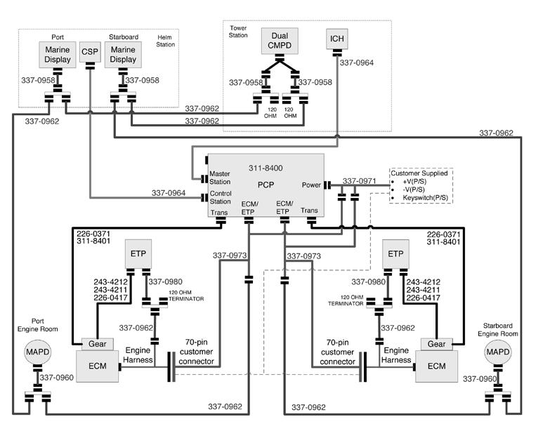
Fig. 03 MSCS II Dual Engine example
The MSCS II system does not use the MJB for power distribution and therefore requires the customer to supply Power, Ground and Keyswitch to the engine 70-pin customer connector and the PCP . Fig . 04 shows a typical example for a dual engine application . The batteries, circuit breakers, terminal blocks, wires, and switches are supplied by the customers .
Fig 05 shows a typical example of customer terminations for cable 337-0971 . The batteries, circuit breakers, terminal blocks, wires, and switches are supplied by the customers .

Fig. 04 MSCS II Dual Engine Customer Wiring Example: Power, Ground, and Keyswitch
Fig. 05 MSCS II Dual Engine PCP Power Termination Cable 337-0971


