
6 minute read
Marine Power Displays


MARINE POWER DISPLAYS COLOR MPD 309-3001 MINI MPD 222-2222 MPD 333-3333
INFORMATION SCREENS
SYSTEM INFORMATION SCREEN
The Marine Power Displays are available in three different models, the Color MPD, the Mini MPD and the MPD . All three units can display the information in this section . The MPD will be used for all examples . The Marine Power Display (MPD) provides current engine and transmission operating data . The screens can be customized to display various engine parameters and MSCS information . The MPD software has been redesigned to include MSCS functions . There are two information screens available, the System Information screen and the Control System Information screen . Pressing the button labeled Menu will display the System Information screen or the control system Information screen . The System Information screen is the first screen displayed by default, however the MPD will retain which information screen was displayed last until a power-off/reset .
The System Information screen will display the current User Name, Software Version, ROM Bootloader Software Version, Unit Serial Number, Unit Location, Engine Location, Display Units, and Vessel Speed Units . Pressing the button labeled Menu will display the System Information menu screen . On this screen, the button functionality is re-defined as shown on the right side of the screen, see figure 3 . If a diagnostic code is active and the diagnostic code window is on screen, the button actions return to their normal definitions . Pressing the up or down arrow button will cause the top menu item (labeled Change Screen) to scroll through the items to be changed (Change Screen, Change User, Change Unit Location, Change Display Units, and Change Vessel Speed Units) and cause the selected data to be displayed in reverse video . Pressing the alarm button will cause the specified parameter to scroll through each available value (i .e . Change Vessel Speed would scroll through Knots, MPH, and KPH) . Pressing the button labeled Exit will return the display to the System Information screen and save any changed data to non-volatile memory .
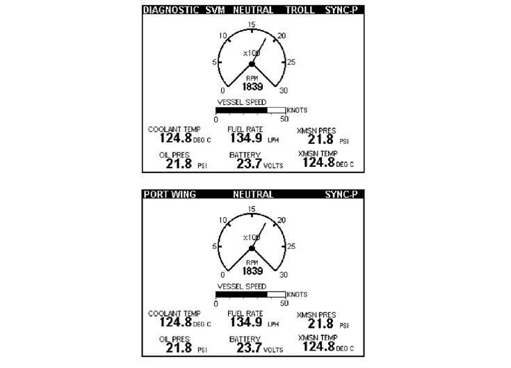
Figure 2 – Information Screens
CHANGE SCREEN
CHANGE USER
CHANGE UNIT LOCATION
CHANGE DISPLAY UNITS
CHANGE VESSEL SPEED UNITS
CHANGE SYSTEM INFORMATION SCREEN

Figure 3 System Information Menu Screens
Pressing the alarm button will cause the Control System Information screen to be displayed . This option is only available if the MPD has detected a Powertrain Control Processor (PCP) on the CAN data link .
Pressing the alarm button will cause the displayed User Name text to scroll through the available user names .
Pressing the alarm button will cause the displayed Unit Location text to scroll through the available location selections . The vessel locations that are available are: Bridge, Port Wing, Starboard Wing, Tower, Engine Room, Aft Station, Fly Bridge, and Bow Station .
Pressing the alarm button will cause the displayed Display Units text to scroll through the available units selections (English and Metric) .
Pressing the alarm button will cause the displayed Vessel Speed Units text to scroll through the available units selections (Knots, MPH, and KPH) .
The Control System Information screen will only be displayed if a Powertrain Control Processor (PCP) is detected on the data link . This screen will display the PCP software part number, Troll Mode, Troll Set Engine Speed, Engine Sync Master, Active Station Location, active Station Button Status, and Active Station Lamp Status . Pressing the button labeled Menu will display the screen shown in Figure 4 . On this screen the button functionality is re-defined as shown on the right side of the screen . However, in the presence of a diagnostic code window button actions return to their normal definitions . Pressing the up or down arrows will cause the top menu item (labeled Change Screen) to scroll through the items to be modified (Change Screen, Change Troll Mode, Change Set Speed, Change Sync Master, and Change Station Location) and cause the selected data to be displayed in reverse video . Pressing the alarm button will cause the specified parameter to scroll through each available value . Pressing the button labeled Exit will return the display to the Control System Information screen and transmit any changed data items to the PCP .
CHANGE SCREEN
CHANGE TROLL MODE
CHANGE TROLL SPEED
CHANGE ENGINE SYNC MASTER
ACTIVE STATION LOCATION

Figure 4 Control System Information Menu Screens
Figure 5 Change Troll Set Speed Menu
Pressing the alarm button will cause the System Information screen to be displayed .
Pressing the alarm button will cause the displayed Troll Mode to scroll through the available troll modes (Traditional and Intelli-Troll) .
Selecting Change Troll Set Speed will display the following screen . Pressing + will increase the set speed by 1 rpm and pressing – will decrease the set speed by 1 rpm . Pressing Save will cause the MPD to send the data to the PCP (and exit the screen), and pressing Cancel will cause the MPD to exit the screen without sending any data to the PCP .
Pressing the alarm button will cause the displayed Engine Sync Master to scroll through the available sync master selections (PORT and STBD) .
Displays the Active Station Location (Bridge, Port Wing, Starboard Wing, Tower, Engine Room, Aft Station, Fly Bridge, and Bow Station) . If the PCP reports that there is no active station, then the MPD will display NONE in the Active Station Location field .

BUTTON STATUS INDICATOR
LAMP STATUS INDICATOR
The Station Button Status indicators display the button status as read by the active control station . • SA – Activate Station Button Status • SVM – Slow Vessel Mode Button Status • SYC – Engine Synchronization Button Status • N – Idle (Neutral) Lockout Button Status • TR – Trolling Mode Button Status
The Station Lamp Status indicators display the commanded lamp status from the active control station . • SA – Activate Station Lamp Status • SVM – Slow Vessel Mode Lamp Status • SYC – Engine Synchronization Lamp Status • N – Idle (Neutral) Lockout Lamp Status • TR – Trolling Mode Lamp Status
SVM Status Gear Position Troll Mode Status
Active Diagnostic Status of Active Station Location
Engine Synchronization Status
Figure 6 CMPD Status Bar Screen
VESSEL STATUS BAR
The status indicators are shown across the top of the screen in reverse video and are only available on parameter screens, except for the diagnostic icon, which is shown on all screens . The following status items are displayed: Diagnostic, Active Station Location, Slow Vessel Mode, Gear Position, Troll Mode, and Sync Mode . The Diagnostic icon overrides the Active Station Location when there is an active diagnostic condition .
*If there is an active diagnostic, the word DIAGNOSTIC will be displayed in place of the active station location .
Parameter Status Display Text
slow Vessel Mode sVM active sVM sVM inactive no text Displayed
gear position forward aheaD
neutral
reverse neUtraL
astern
gear Lockout gear L/o active
troll Mode troll active troLL troll inactive no text Displayed
engine sync Mode synchronized port sYnC-p
synchronized stbD sYnC-s
port Master CrUise-p sync Cruise active
stbD Master CrUise-s sync Cruise active
active station* sync not active no text Displayed
bridge briDge port Wing port Wing stbD Wing stbD Wing tower toWer engine room eng rooM aft station aft station fly bridge fLY briDge bow station boW station
CABLES REQUIRED
Where Used: Connects the PCP and MPD displays into the J1939 data link . The J1939 data link can not exceed 40 meters (131 ft .) .
Requires:
MPD drop cable – 225-6112 Tee to Tee cable – 225-6107 6-pin Tee – 221-6506 Termination resistor – 208-0432


