
8 minute read
Electronic Troll Processor


ELECTRONIC TROLL PROCESSOR (ETP) INSTALLATION 256-4883
When the transmission is equipped with an optional electronic troll valve, the ETP will provide the trolling interface between the Powertrain Control Processor (PCP) and the electronic transmission . The ETP is responsible for providing the trolling signals to either Twin Disc or ZF electronic transmissions . The ETP receives the troll command (% slip) from the PCP, converts the message into a current/voltage and controls the transmission troll valves accordingly . The ETP also measures the shaft speed and transmits it on the J1939 data link to be displayed on the MPD .
ETP CONNECTIONS
Signal Requirements Max Slip Min Slip Troll On/Off Part Number
Twin Disc 5 V 0V yes 243-4211 or 243-4212 Reintjes 2 V 4 V yes 243-4211 or 243-4212 ZF-325, 350, 550, 655 200 mA 300 mA no 226-0417 ZF 2555 200 mA 300 mA no 226-0417 ZF-2000 150 mA 300 mA yes 226-0417 ZF-1900/2500 450 mA 160 mA yes 226-0417 ZF-4500 . . .750 450 mA 160 mA yes 226-0417 ZF-2000 1 .2 V 3 .8 V yes 243-4211 ZF-1900/2500 1 .2 V 3 .8 V yes 243-4211 ZF-4500 . . .750 1 .2 V 3 .8 V yes 243-4211 ZF-2060 A 150 mA 300 mA yes 226-0417
ZF Troll Valve ZF 1900, ZF 2500, ZF 4600
Requires: 102-8804 Receptacle Kit (includes 3E3376 receptacle and 3E3377 wedge) 1Q5094 Plug Assembly — inline connector or 8T9605 Plug Assembly — right angle connector
ZF Connector Wire Name 4-pin Deutsch
A Proportional Valve B+ 1 B Solenoid ON/OFF B+ 4 C Solenoid ON/OFF B+ 3 D N/C E N/C F Proportional valve B- 2
ZF Gear Connection ZF 1900, ZF 2500, ZF 4600
Requires: 102-8805 Receptacle Kit (includes 3E3382 receptacle and 3E3383 wedge) 1Q5094 Plug Assembly — inline connector or 8T9605 Plug Assembly — right angle connector
ZF Connector Wire Name 6-pin Deutsch
A FWD + 1 B REV + 2 C N/C D N/C E N/C F Common 3 and 6
Measuring Troll Valve Current
Step 1 Disconnect the troll 4-pin connector and remove pin one from both connectors . Pin 1 Pin 1 Step 2 Set the voltmeter to measure current Step 3 Connect the meter Keep pin one out from both connectors and connect the 4-pin connector together . Connect the red probe from the meter to the socket wire from ETP) . Connect the black probe to the pin (Harness to Troll Valve) . Turn the system on, engine off . Activate troll and move the throttles while measuring the current .
Pin 1 Pin 1
To ETP To ETP
verify that you verify that you are using the are using themeter input meter input for current for current Set meter to Set meter tomeasure current measure current on the mA scale on the mA scale
To ETP
TWIN DISC PROFILE INSTALLATION
TWIN DISC MGX/ETROLL & MG GEARS ETROLL INSTALLATION 4-20 mA Troll Command
NIN = Not In Neutral
TWIN DISC MGX/ETROLL INSTALLATION 0-5 VDC Troll Command
SHAFT SPEED SENSOR INSTALLATION 226-3424
The ETP provides an input to monitor shaft speed . Shaft speed can be displayed on MPD . Use the MPD Builder program to customize the MPD screen to display Shaft Speed .
Magnetic Band Installation
Install the magnetic band around the propeller shaft . Tighten the magnetic band so that it does not slide or move around he shaft . Do not exceed 8 in/lbs on the tightening screw .
SHAFT SPEED SENSOR INSTALLATION
(cont)
Fabricate a bracket to secure the shaft speed sensor above the magnetic band . The bracket should be installed radially in line with the magnets on the magnetic band . Position the clamp band under the shaft speed sensor and adjust the sensor so that it is touching the clamp . Loosen the speed sensor 1/4 turn to create an air gap (1/32”) between the shaft speed sensor and the tightening screws of the magnetic band .
Shaft Speed Pulses Per Revolution
Number of shaft speed sensor pulses per shaft revolution . This number is dependent on the number of magnets installed on the shaft speed magnetic band . The standard value is 4 . This value should be programmed to number of magnets divided by 2 .
Options Default 0 to 250 pulses 4 pulses per per revolution revolution
ETP CALIBRATION (USING ET)
! WARNING
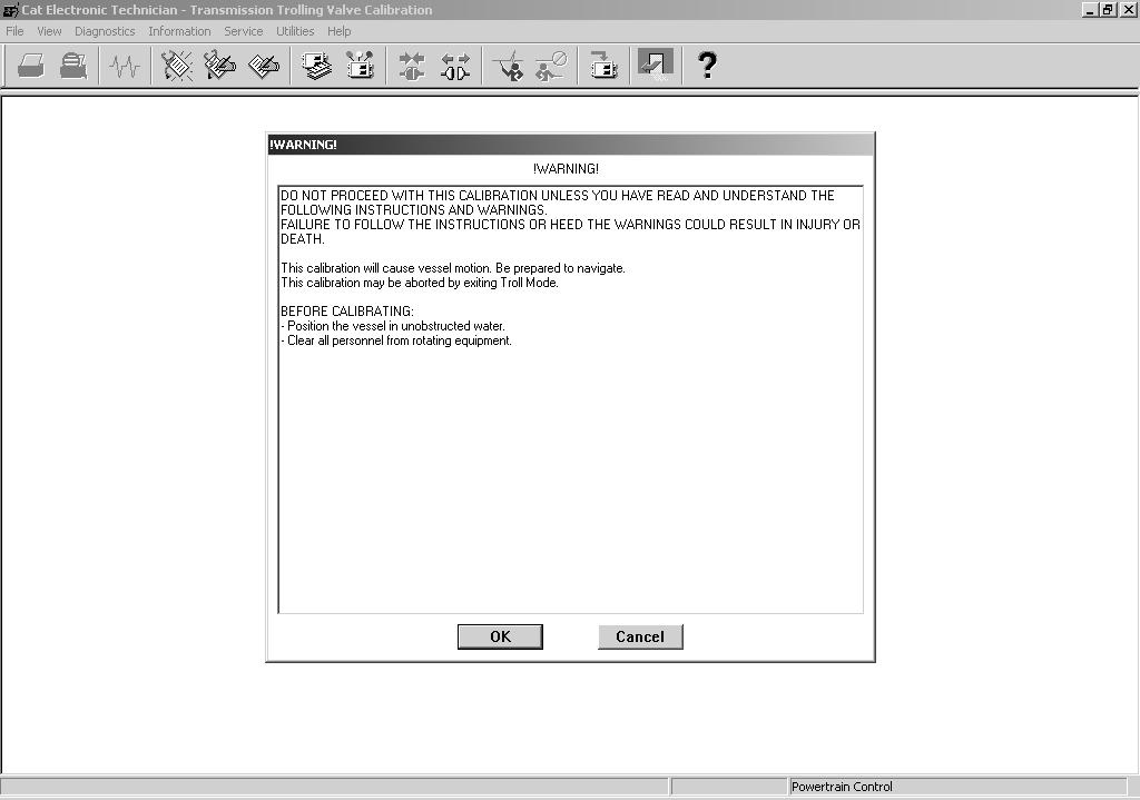
Do not proceed with this calibration unless you have read and understand the following instructions and warnings. Failure to follow the instructions or heed the warning could result in injury or death.
This calibration will cause vessel motion, be prepared to navigate. This calibration may be aborted by exiting Troll mode.
Before Calibrating: Position the vessel in unobstructed, navigatable water. Clear all personnel from rotating equipment.
1 . Turn the keyswitch ON engine OFF . Boot up ET and access Service >
Calibrations > PCP Transmission Valve Calibration .

2 . The warning screen will appear . Read the warning carefully and notify any passengers that the vessel will be moving while the calibration procedure is performed . Then click OK .
3 . The Select Components To Calibrate Screen will appear . Click on the appropriate calibrations needed for the vessel . If the vessel is equipped with a single engine, click on the Port calibrations and verify that the engine location is programmed to PORT .

Single engine vessel

4 . Select the parameters to calibrate and click on Begin .
5 . To begin the calibration sequence; • Turn the keyswitch ON and start the engine . Allow the engine and transmission to reach normal operating temperatures . • Turn on Traditional Troll . This can be done using the MPD . Scroll to the Control System Information Screen and change Troll Mode to
Traditional .
• Place the throttles at 100% or W .O .T . • Click on Next


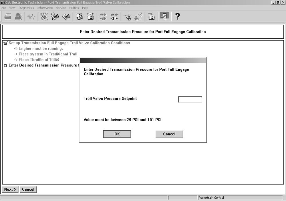
6 . Enter the pressure set point for full engagement for the Port engine . This value can be found on the transmission information plate, operator’s manual, or by using ET while monitoring transmission pressure during transmission lock-up .
7 . Click OK .
8 . ET will calibrate the Port Transmission full engage value .

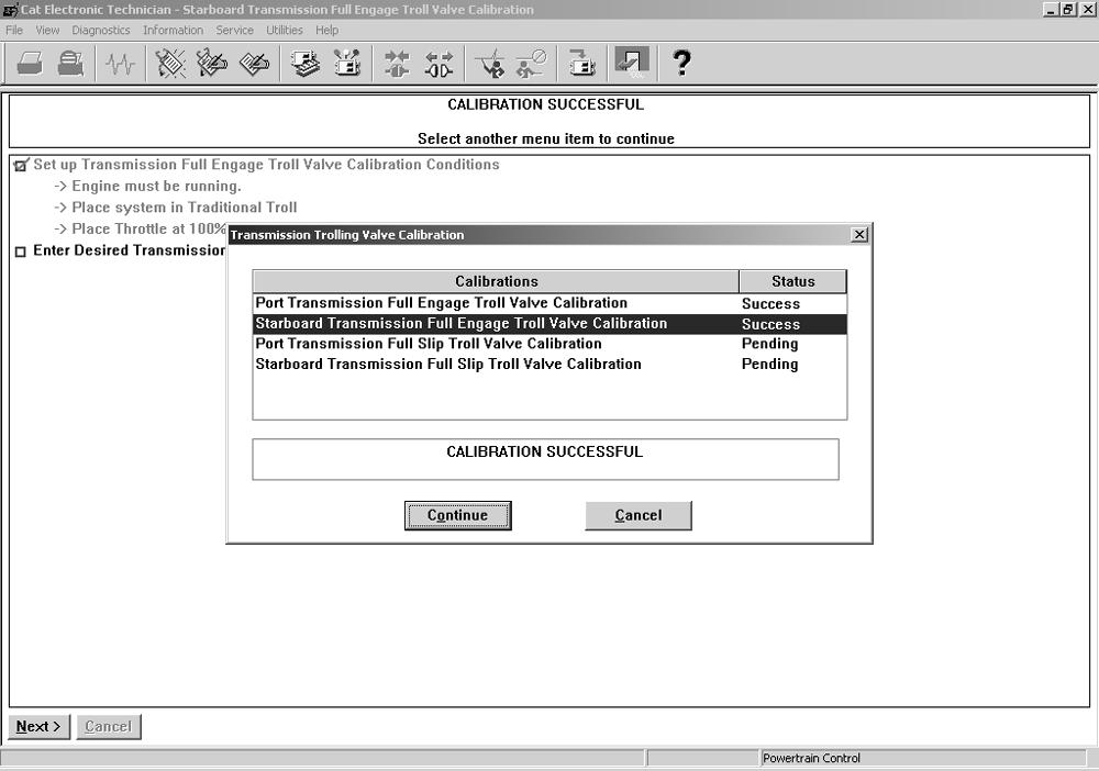
9 . The Successful Calibration Screen will appear . Click on Continue .

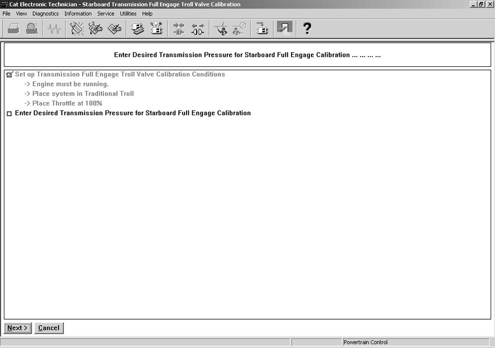
10 . Allow the Starboard engine and transmission to reach normal operating temperatures . • Place the throttles at 100% or W .O .T . • Click on Next

11 . Enter the pressure set point for full engagement for the Starboard engine .
This value can be found on the transmission information plate, operator’s manual, or by using ET while monitoring transmission pressure during transmission lock-up .

12 . ET will calibrate the Starboard Transmission full engage value .
13 . The Successful Calibration Screen will appear . Click on Continue .
14 . Allow the Port engine and transmission to reach normal operating temperatures . • Place the throttles at 0% throttle or low idle . • Click on Next

15 . Enter the pressure set point for full slip for the Port engine . This value can be found on the transmission information plate, operator’s manual, or by using ET while monitoring transmission pressure during full slip . Click on OK .

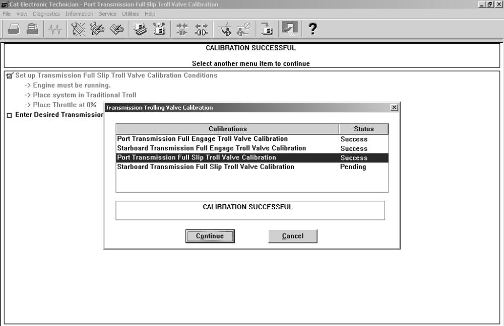
16 . ET will calibrate the Port Transmission full slip value .

17 . The Successful Calibration Screen will appear . Click on Continue .
18 . Allow the Starboard engine and transmission to reach normal operating temperatures . • Place the throttles at 0% throttle or low idle . • Click on Next

19 . Enter the pressure set point for full slip for the Starboard engine . This value can be found on the transmission information plate, operator’s manual, or by using ET while monitoring transmission pressure during full slip . Click on OK .

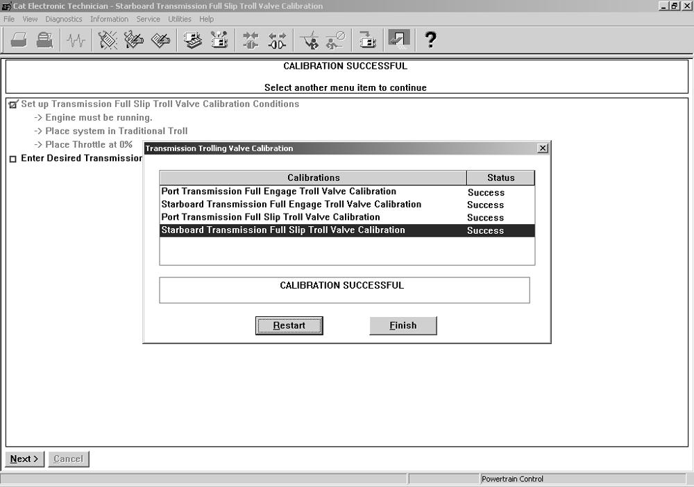
20 . ET will calibrate the Starboard Transmission full slip value .

21 . The Successful Calibration Screen will appear . Click on Finish .
TRANSMISSION PRESSURE SENSOR INSTALLATION Installation on the ZF Supershift transmission

Optional adapter block, 18 mm threads . The adapter block can be used to install the transmission pressure sensor . This location will read clutch applied pressure for forward and reverse and 0 pressure when the gear is in neutral .


