12 minute read
PORTABLE REMOTE PROPEL STATION


MISCELLANEOUS CONTROLS
Located about the machine are various miscellaneous controls and monitors which would be used with optional equipment or do not fit in the previously described groups.
PORTABLE REMOTE PROPEL STATION (Optional)
The portable remote propel station is located in an enclosure under the operator’s cab on the right side of the machine. In addition to storing the portable station the enclosure includes 40 feet of cable and an enabling switch to energize or de-energize the station. Another enabling switch and plug in socket are located at the front left corner of the drill main frame. The station includes two joysticks, one for each crawler frame; an emergency stop push-button; a propel speed selector; and a red indicator which will light up when the station is energized.
PORTABLE REMOTE PROPEL STATION
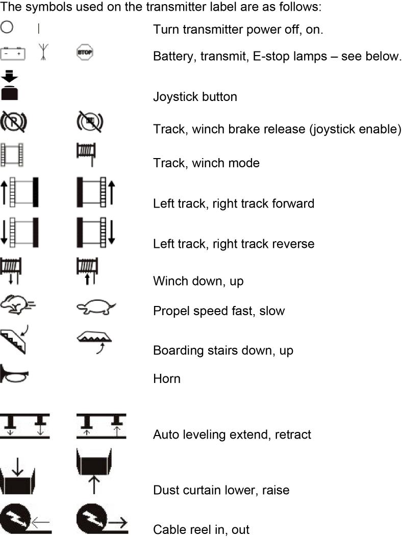
RADIO REMOTE PROPEL STATION (Optional)
The radio remote propel station is located in the operator’s cab. To enable the station, position the operating mode switch located on the left control console to Remote Propel. The station includes two joysticks, one for each crawler frame; an emergency stop push-button; function selector switches as described below; and an indicator which will light up when communication is established between the transmitter and the reciever. There is also an indicator light for the status of the e-stop and the battery charge.

PRESTART CHECKS
Before starting the drill, inspect it to ensure it is ready to be put into operation. Failure to make such a routine check could result in unnecessary downtime. For example, an undetected oil leak could result in a dry gear case, which would lead eventually to excessive gear wear or destruction, seized bearings, or other mechanical problems. A few minutes spent inspecting the machine often results in considerable savings in time and machine efficiency. This inspection should be performed before each shift.
EXTERNAL INSPECTION
1. Check areas around and under the machine for signs of water or lubricant leaks. If single droplets of water or lubricant are noticed, leakage is minimal. Determine the source of the leak and make note of it on the log sheet. If pooling of water or lubricant is noticed, determine the source and take remedial action immediately.
15
LH VIEW
12
RH VIEW
FRONT OF MACHINE
16 9
10 11
6 8 1
7 3 2 4 14
13
8 5 8 FRONT OF MACHINE
11
10 9
16
4 2 3 1
7 8 6
insp6640
2. Inspect the crawler belts for broken or cracked pads, missing lock pins, loose track pins, and proper crawler belt tension. 3. Check the drive tumbler gearcase, hydraulic motor and hoses for leaks. Check the lubricant level in the drive tumbler gearcase. 4. Inspect the crawler frames for cracks and dirt or ice buildup. Check the rollers and tumblers for proper lubrication, free operation, and dirt or ice buildup. Check axle attachment pins and bolts.
5. Check the dust curtains for tears. Be sure that the curtains are not frozen to the ground or covered with cuttings. 6. Inspect the trail cable for proper placement out of the line of travel of the drill. Inspect the insulation for cuts or abrasion. Make sure the cable is kept out of water and away from sharp rocks. Have an electrician inspect the strain relief device and the condition of the cable where it enters the machine.
CAUTION: The machine trail cable carries a lethal voltage. Handle the cable in an approved manner with approved rubber gloves and insulated hooks or tongs.
7. Inspect the underside of the machine for cracks, loose hoses or wires, dirt or ice accumulation, or other deterioration or damage. If loose wires are noted, do not touch them but notify an electrician immediately. 8. Inspect the leveling jack spuds for proper lubricant covering. Inspect the leveling jack pads for cracks, broken or missing pins, or excessive dirt accumulation. 9. Inspect the mast braces and locking pins. Replace missing or defective components immediately. Verify that all adjusting bolts are properly adjusted. Check all hoses and cylinders for leaking.
CAUTION: Use a safety belt and lanyard to protect against falls when climbing on the mast braces or working on the machinery house roof.
10. Inspect the mast hinge pins for loose or missing keepers or bolts. Replace missing or damaged parts immediately. Check the pins for sufficient lubrication and lubricate if necessary. 11. Inspect the mast hoist cylinders for loose or missing pins or keepers, oil leaks, damaged hoses or structural damage. Repair or replace any missing or damaged components immediately. 12. Inspect the mast structure for bent or broken chords or plates, loose or broken parts, proper rack lubrication or excessive rack wear. Inspect ladders, handrails and platforms for broken or missing parts. Repair or replace broken or missing parts immediately. 13. Check the main air flex hose, lubrication lines, and electric lines running from the mast to the rotary drive/pulldown unit for interference with the mast or excessive wear or leaks.
14. Check the safety restraint cables on the mast. Be certain that the cables and supports are in good repair with no cracks, missing or loose hardware or any damage that could affect their effectiveness.
15. Every 160 hours inspect the upper auxiliary winch sheaves. All pins, keepers and hardware should be secured.
16. Check the machinery house air filtering fan duct to see that it is clear of obstructions. 17. Inspect dust collector hoses for integrity.
ONBOARD INSPECTION
1. Inspect the air compressor lubrication lines for leaks. Correct any leaks found immediately. 2. Check the condition of the air compressor intake filter. Replace the filter cartridge if the red flag is visible in the service indicator. Empty the dust hopper and clean the pre-cleaner element. Inspect the housing and ductwork for damage or leaks. Repair or replace leaking components. 3. Check the oil level in the hydraulic tank. Fill the tank to the proper level as described on the instruction plate on the tank. 4. Check hydraulic system for leaks. Correct all leaks immediately and clean up all oil spills immediately. 5. If the machine is equipped with a bit lubricator for the main air system, check that the lubricator is full.
6. Inspect the automatic lubrication central pumping stations for proper operation. Check the supply of lubricant; refill tank as necessary.
7. Close and lock all electrical cabinet doors.
CAUTION: Assume all parts inside of the electrical cabinets are energized. All electrical components should be serviced by qualified electrical personnel only.
8. Inspect the compressor radiator and fan. Check for signs of deterioration or damage to hoses, valves, fittings, etc. Check for leaks at all joints. Check the radiator core for blockage by dust, dirt, leaves, paper, etc. and clean as necessary 9. Check the operator’s display terminal for any faults. 10. Inspect the machinery house for general cleanliness. Clean all dirt and debris from the machinery house.
CAUTION:Do not use compressed air to clean the machinery house. Compressed air will only move the dirt around. Use a vacuum cleaner to remove the dirt from the machine. Failure to clean the inside of the machinery house will cause damage to many of the components located there.
11. Inspect the auxiliary winch and auxiliary winch line. 12. Check the oil level in the pump drive gearbox. Fill with recommended oil to the proper level. 13. Check all controls for free operation. Return all controls to the OFF or SET position. 14. Inspect the operator’s cab for housekeeping and cleanliness. Clean dirt and debris from the cab. Clean the windows to give full visibility for proper operation.
CAUTION:Do not use compressed air to clean the operator’s cab. Compressed air will only move the dirt around. Use a vacuum cleaner to remove the dirt from the cab.
15. Inspect the tool wrenches for free operation, broken or missing parts, proper lubrication, lubricant leaks or dirt accumulation. Repair or replace parts as necessary and clean the drilling platform.
CAUTION: Before working near or under the rotary drive/pulldown unit, make sure all of the operator’s controls are off and tagged and the hoist brake set to prevent movement of the unit. Serious personal injury or death could result should the rotary drive/pulldown unit fall when personnel are working near or under it.
16. Inspect the automatic breakout wrench for free operation, broken or missing parts, proper lubrication, lubricant leaks or excessive dirt accumulation. Repair or replace parts as necessary. Be certain that the breakout wrench is retracted.
17. Inspect the pipe racks for broken or missing parts, proper operation, dirt accumulation, or lubricant leaks. Be certain that the upper gate is closed and that the rack is in the stored position. 18. Inspect the guide bushing for excessive wear or dirt accumulation. Also inspect the retainer lugs to be sure they are intact. Do not operate the machine without both retainer lugs intact and securely welded to the deck. 19. Inspect the tool string for excessive wear, dirt accumulation, bent pipe and secure joints. The bit cones and bearing should be in good condition. Manually turn the cones to make sure they turn freely. 20. Inspect the rotary gear case for lubricant leaks, damaged lines, dirt accumulation and other damaged or missing parts. Check the lubricant level in the gearbox. Fill to the recommended level with an approved gear lubricant. Check the rotary motor ventilation inlets for leaves, paper, rags, etc. blocking the flow of air. 21. Inspect the rotary drive unit for excessive wear or dirt accumulation. Inspect the guide rollers for proper adjustment and excessive wear. Check for loose or missing bolts and bent or cracked structural members.
22. Inspect the pulldown unit for excessive wear or dirt accumulation. Inspect the rack pinions for excessive wear, proper lubrication, and tight retainer bolts. Inspect the guide rollers for proper adjustment and excessive wear. 23. Inspect the pulldown gearcase for lubricant leaks, dirt accumulation and other damaged or missing parts. Check the lubricant level in the gearbox. Fill to recommended level with an approved gear lubricant . Check the pulldown motor ventilation inlets for leaves, papers, rags, etc. blocking the flow of air. 24. Check the hoist brake for proper operation. 25. Check the dust or chip deflector for loose or missing parts, excessive wear or dirt accumulation. The deflector should seal around the drill pipe securely. 26. If the machine is equipped with a fire suppression system, perform any applicable checks or inspection as described in the fire suppression system owner’s manual. 27. If the machine is equipped with a dust collector system, inspect the filter dessicant color. Change dessicant if required.
PRESTART LUBRICATION
Lubrication is an extremely important job. Most drills come equipped with automatic lubrication systems that lubricate most of the necessary points at regular intervals. These systems, although automatic, are not foolproof. Broken lines, dirty lubricant, faulty feeders, and a whole range of other problems can cause wearing parts to loose lubrication. For this reason, it is important that all lubrication points be inspected every shift to verify that they are receiving lubrication. Also, there are several points for lubrication that either need lubrication very infrequently, or are not possible to pipe into the automatic system. These points will need lubrication applied manually.
The lube charts in Section 3 of this manual provide the location and frequency of lubrication.
START-UP
Start-up of the drill is not a difficult operation, but it is very important. Improper start-up could cause various safety and operating difficulties as well as damage to the machine. Following the step-bystep procedure listed below to start the machine will help reduce the possibility of accidental injury or machine damage.
MACHINE START UP
NOTE: THE MACHINE IS TO BE STARTED ONLY AFTER THE PRESTART INSPECTION AND LUBRICATION AS DETAILED EARLIER IN THIS SECTION, HAVE BEEN COMPLETED.
1. Go into the operator’s cab and verify that all controls on the operator’s console are in the off or neutral position. Be sure that the EMERGENCY STOP push-button is in the pulled-up position.
NOTE: ON SOME MACHINES THERE ARE TWO OR MORE EMERGENCY STOP PUSHBUTTONS. BE SURE THESE PUSH-BUTTONS ARE IN THE PULLED-UP POSITION.
2. Go to the machinery house to the low voltage start cabinet. Turn on the main compressor breaker.
3. On the low voltage cabinet turn all the breakers to the ON position.
4. On the programmable controller cabinet verify that the lockout control push-button is in the RELEASED position.
5. Press the air compressor start push-button on the programmable controller cabinet to start the main compressor.
NOTE: If the ambient temperature is below 32°F (0°C), the machine will normally use special fluids in the hydraulic system and/or heaters for the system.
When the machine is shutdown, temporarily or for an extended time, power should be left on the machine to maintain heater operation. If power is removed at shutdown, the machine fluids should be warmed to at least 32°F (0°C) before attempting to start the machine.
MACHINERY CHECK
The following is a list of points and equipment that should be checked for proper operation immediately following start-up of the drill. If operating difficulties are not found during this procedure, they probably will not be noticed until some point in time at which the system or component will cease to function and cause serious damage to the machine.
1. Check the main air system for leaks.
2. Verify that the air compressor radiator fan is operating correctly. Check the coolant system for leaks.
3. Check for leaks in the hydraulic system.
BREAK-IN OF NEW COMPONENTS
When a machine is new, is returned to service after a long period of storage, or is returned to service after major repairs, certain precautions must be taken upon initial start-up and for a time following the start-up. These precautions are necessary to insure that the full service life of the components is realized.
ROTARY DRIVE UNIT BREAK-IN
Break-in of the rotary gear case is limited to reduced loading during the first 100 hours of operation and a complete oil change at the end of the break-in period.
This break-in period applies only to new gearcases or gearcases in which a new gear has been installed.
HOIST/PULLDOWN GEARCASE BREAK-IN
Break-in for the hoist/pulldown gearcase is limited to reduced loading during the first 100 hours of operation and a complete oil change at the end of the break-in period.
The break-in period applies only to new gearcase or gearcases in which a new gear has been installed.
ELECTRIC MOTOR BREAK-IN
Break-in of the rotary and hoist/pulldown motors is limited to reduced loading and inspection for the first 8 hours of operation. This break-in period is intended to spot any problems in the motors before