8 minute read
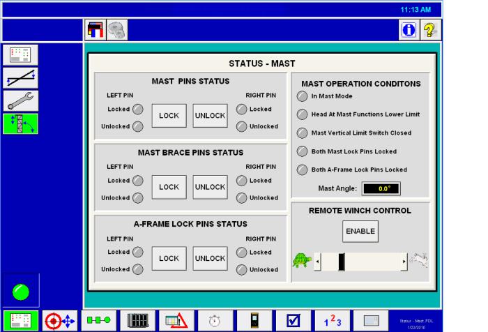
MAST STATUS SCREEN


4. To level the machine manually, use the three jack switches and the automatic leveling screen on the operator’s display terminal. The operator uses control switches on the right-hand console and observes the operator’s display screen.
5. Lower all four leveling jacks until they are resting on the ground. Then, starting with the low side (left or right) of the drill, slowly lower the jacks until the weight of the machine is resting on them. The leveling jack controls should be operated in pairs while doing this operation. This reduces the twisting of the drill frame. Once the weight of the machine is resting on the downhill side leveling jacks, slowly lower the uphill side leveling jacks until the machine weight is resting on them. The machine need not be raised a great deal during this operation, since the purpose is only to get the weight of the machine resting on the leveling jacks.
CAUTION: During this and subsequent leveling procedures, it is important that the drill stays as close to level as possible. Care should be taken especially when working on steep grades.
6. Once the machine weight is resting on the leveling jacks, the machine may be leveled. Starting with the downhill side of the machine, lower the two side leveling jacks to bring the machine into side-to-side level as observed on the operator’s display terminal screen. Then, once the machine is level from side-to-side, operate the leveling jack controls for the downhill end of the machine to bring the machine into level end-to-end as observed on the operator’s display terminal screen.
7. Once the machine is level, make sure that the weight of the machine is off of the crawlers. The preferred method of doing this is to raise the machine until the closest point of the lower rollers to the crawler belts is 2" to 7" (5.1 to 17.8 cm). This assures that the machine is resting on the leveling jacks while maintaining a low center of gravity.
MAST RAISING AND LOWERING
The mast on this machine is normally left in the raised position for most situations including propelling from hole to hole on a blast pattern. Lowering the mast is necessary under three conditions:
1. Maintenance work is not possible or too dangerous to perform with the mast up.
2. Long moves over 1,000 feet (304 m) where the drill will be towed into position, propelled at high speed, or be loaded onto a trailer.
3. Any situation when steep slopes are encountered. Contact Caterpillar Global Mining Service Department if unsure of slope limitation for propelling.
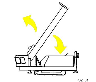
MAST RAISING
CAUTION: Raising or lowering the mast is a two-person job. Do not attempt to raise or lower the mast without the assistance of a helper familiar with the procedures involved.
CAUTION: During the mast raising procedure personnel should be kept clear of the machine and the area immediately surrounding the machine, especially the front of the machine. No one is to be allowed on the mast, operator’s cab roof, or machinery house roof while the mast is in the air. Failure to heed this caution may result in the death or serious injury of personnel struck by the mast should it fall for some reason.
CAUTION: Limitations exist as to the length, diameter, wall thickness and number of drill pipes that may be stored in the pipe racks when raising or lowering the mast. Refer to the pipe size limitation chart in the appendix before attempting to raise or lower the mast. Failure to comply with these limitations will overload the mast, mast support and hydraulic system possibly causing loss of control of the mast.
1. Inspect the mast and machine exterior to ensure that all wires, hoses, cables, etc. are clear of the machine to prevent damage to the machine or equipment during the raising procedure. Check that the mast cylinder pins, mast hinge pins, and mast brace pins are in place and secured. Verify on the operator’s display terminal operator’s display screen that no reference to A-frame pins is shown. Verify that the operating mode selector switch is in the DRILL mode.
2. The main air compressor motor must be energized. Move the operation selector switch to the MAST/WINCH position. Slowly raise the mast by lifting and then slowly pushing the mast joystick, located on the right control console, forward. As the mast reaches an angle of 70 degrees it will begin to go over center and tend to come into the vertical position by itself. Care should be used once the mast has gone over center since the speed of the mast will increase sharply.
CAUTION: The mast joystick should be moved away from and returned to the neutral position very slowly. Sudden starts and stops can be damaging to the mast and hydraulic system. Be extremely cautious as the mast approaches 70 degrees as once the mast goes over center only a very slight movement of the joystick is necessary to cause motion in the mast.
NOTE: Pay close attention to the hoses, wires and cables that run between the mast support and the mast to prevent damage to the machine as the mast is being raised. Have a helper watch from a safe position on the left side of the machine as the mast is going up.
3. Once the mast is vertical, move the mast lock switch located on the mast screen on the operator’s display to the LOCK position to lock the mast in the vertical position. Mast Pins Locked light on operator’s display screen will illuminate when mast is locked in position. Turn the mast brace lock switch to the LOCKED position to secure the mast and brace in the vertical position.
NOTE: When moving the mast for angle hole drilling, on machines with mast lengths of 65 ft (19.8 m) or more, the drill pipe must be stored in the racks and the rotary head lowered to its lowest position.
4. If the mast is to be set up for angle drilling move the A-frame lock switch and the mast brace lock switch to the UNLOCK position to release the A-frame front leg lock pin and mast brace lock pins. The readout (A-Frame Pins Unlocked and Mast Brace Pin Unlocked) will show up on the mast status screen on operator’s display screen.
MAST STATUS SCREEN
5. Verify that the operation mode selector switch is still in the mast/winch position, then lift and pull the mast joystick slowly to the rear. Slowly lower the mast to the desired drilling angle, then turn the mast brace lock switch to the LOCKED position to secure the mast and brace in the desired position.
MAST LOWERING
NOTE: Refer to cautions at beginning of mast raising.
To lower the mast:
1. Level the machine.
2. Remove the drill pipe from the rotary drive unit and store it in the pipe racks. Remove the bit and stabilizer from the machine. Clear the drill deck of all tools and materials which could fall off during the lowering procedure. Secure the auxiliary winch hook. Be sure the auxiliary winch line is secured to the mast. Raise the dust curtains. Lower the rotary/pulldown unit to its lowest position.
3. Check the condition of the mast hinge pins, lugs and cylinder pins.
4. If the machine is set up for angle drilling and the mast is at an angle proceed to step 4. If the machine is set up for vertical drilling proceed to step 5.
5. Turn the mast brace lock switch to the UNLOCK position to release the mast lock pins, then raise the mast to the vertical position. Turn the A-frame lock switch to the LOCK position to lock the A-frame front leg. The readout (A-Frame Pins Locked) on the operator’s display will appear when the A-frame pins are in the LOCKED position. Now proceed to step 5 to lower the mast.
6. If the mast lock pins and/or mast brace lock switch have not been released, turn the switches to the UNLOCK position to release the pins. The readout (Mast Pins Unlocked and Mast Brace Pins Unlocked) will be shown on the operator’s display when the pins are released.
7. Slowly lower the mast by lifting and then pulling the joystick to the rear. As the mast moves away from the vertical position, its speed will increase. Gently reduce the lowering speed by moving the joystick toward neutral.
CAUTION: The joystick should be moved away from and returned to the neutral position very slowly. Sudden starts and stops can be damaging to the mast hydraulic system. Be extremely cautious as the mast approaches the mast rests, as only a slight movement of the control is necessary to cause motion in the mast. Lay the mast in the mast rests gently to prevent damage to the mast or machine house.
NOTE: Pay close attention to the hoses, wires and cables that run between the mast support and the mast to prevent damage to the machine as the mast is being lowered. Have the helper observe the machine from a safe position on the left side of the machine as the mast is coming down.
NOTE: Do not allow the mast, especially if near horizontal to lower too quickly. Damage may result from the mast hitting the mast reststoo hard.
8. Once the mast is resting in the mast rests, inspect the mast and the mast support to verify that no hoses, wires or cables are kinked or damaged. Repair any damages found immediately.
PULLDOWN MACHINERY OPERATION
Use of the pulldown machinery is necessary during the tool handling and the drilling procedures. The pulldown machinery supplies power to either raise or lower the rotary/pulldown unit. Power is supplied to the pulldown gearbox by an electric motor.
To operate the hoist/pulldown machinery proceed as follows;
1. Move the operating mode selector switch to the DRILL position.
2. Turn the hoist/pulldown selector switch to either PULLDOWN, HOIST HIGH, HOIST LOW, or PIPE RACK/JOINT.
For this procedure, turn the switch to the PULLDOWN position.
For a review of each switch position, refer to HOIST/PULLDOWN SPEED SELECTOR SWITCH.
3. Press the drill/propel control ON push-button. The Control Enable indicator will show on the operator’s display screen.
4. Turn the hoist brake switch to the RELEASE position. The Head Brake Released indicator will appear on operator’s display screen.
5. Rotate the hoist/pulldown rheostat in the hoist direction to hoist the rotary/pulldown unit. The farther the rheostat is turned to the right the faster the unit will be raised.