5 minute read
Annunciator Software Configuration


TABLE 9 LED COLORS
LED COLORS
ROW LED 1 LED 2 ROW LED 1 LED 2 ROW LED 1 LED 2
1 Red Amber 7 Red Amber 13 Green Amber 2 Red Amber 8 Red Amber 14 Green Amber 3 Red Amber 9 Red Amber 15 Red Green 4 Red Amber 10 Red Amber 16 Red Green 5 Red Amber 11 Red Amber 6 Red Amber 12 Red Amber
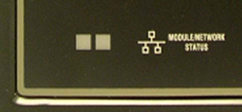
MODULE STATUS LED
A red/green pair located at the bottom of the EMCP 3 GSC, is used to report Module/Network Status. The various states indicated are explained in Table 10 below.
TABLE 10 ANNUNCIATOR MODULE / NETWORK STATUS LED BEHAVIOR
BEHAVIOR EXPLANATION
Red solid CAN data link diagnostic. For example: the module is wired wrong (Data Link), wrong cable, or no terminating resistor. Green solid CAN data link OK Green flashing No CAN data link diagnostic, but no communication detected. Hooking the Annunciator up with the power on.
Red/Green flashing No application software loaded
ANNUNCIATOR SOFTWARE CONFIGURATION
The Annunciator is field-programmable using the Caterpillar® Service Tool. It is also flash programmable to update software using the Caterpillar® Service Tool. The service tool software must be installed on a Windows PC. The Caterpillar communication adapter must be connected between the PC and the J1939 data link on which the target Annunciator is connected. (The service tool may be connected to the EMCP 3 GSC Accessory Data Link service connector). When connecting to the Annunciator, the user will first see the Module Summary screen shown in FIGURE 52.
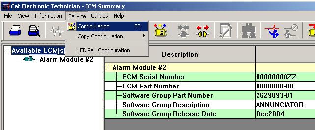
FIGURE 52: CATERPILLAR ® SERVICE TOOL ANNUNCIATOR SUMMARY SCREEN
This screen shows module information such as Serial Number, Part Number, Software Group Number, and Software Release Date.
GLOBAL ACKNOWLEDGE
The Annunciator can be configured to both initiate and respond to an Event Acknowledge message over the J1939 data link. If this setpoint is enabled, the Annunciator events may be acknowledged directly on the Annunciator by pressing the Alarm Acknowledge button or remotely by pressing the Alarm Acknowledge button on the EMCP 3 GSC or by pressing the Acknowledge button on another Annunciator that is on the same data link. Acknowledging events also silences the horn. The default setting for this setpoint is DISABLED, but it can be enabled from the Service Configuration menu item.
ECU INSTANCE NUMBER
The Module Description will also indicate a number that identifies the Annunciator uniquely from any other Annunciator modules on the (Primary or Accessory) J1939 data link. In this example, the service tool is connected to Alarm Module #2. This number is called the ECU INSTANCE and it is programmable. To program the Annunciator to a different ECU Instance number, enter the Configuration Screen by selecting the Service Configuration, as shown in FIGURE 53. The service tool configuration screen, shown in FIGURE 54, identifies the serial number of the Annunciator that is connected. This is important in matching the desired ECU Instance to the actual hardware. In this example, the Annunciator will be programmed to ECU Instance #1. To do this, select the ECU Instance row, and double click on the current ECU Instance. A dialog box will open, allowing entry of the new ECU Instance. Type a numeric value, 1, 2, 3, or 4 and click OK. When you click OK, the service tool software will automatically restart and reconnect to the data link. Upon reconnecting, the summary screen will now show the new module name, based on the ECU Instance. In this example, the new module name will be Alarm Module #1.
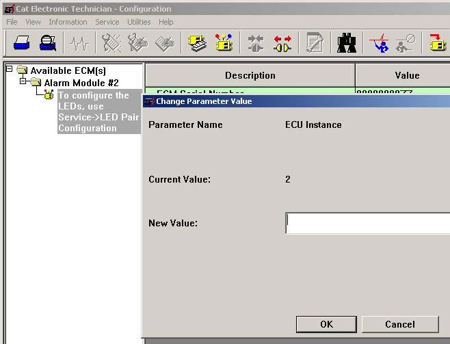
FIGURE 53: CATERPILLAR ® SERVICE TOOL ANNUNCIATOR CONFIGURATION SCREEN
CONFIGURING ANNUNCIATOR LED BEHAVIOR
To configure the behavior of the LED pairs, enter the LED Pair Configuration screen by selecting Service LED Pair Configuration. An example of the LED Pair Configuration screen is shown in FIGURE 54. Each LED pair has four parameters required to configure it. It is best to configure the four columns in order from left to right; first Trigger Condition, next Severity Level, then Suspect Parameter Number, and finally Failure Mode Identifier (if required). The reason for the order is because the value set in one column affects the choices available in the subsequent columns. If a field is grayed out, it is not available due to conditions set in previous columns.
TRIGGER CONDITION
There are three possible selections for Trigger Condition: SPECIFIC EVENT, GENERAL EVENT, and
DISABLED. SPECIFIC EVENT is used to assign an LED pair to a specific data link parameter, such as Oil Pressure, Engine Speed, Coolant Temperature, etc. The desired parameter must be chosen in the Suspect Parameter Number column. GENERAL EVENT is used to assign an LED pair as a general alarm or shutdown indicator. When configured as General Event, the LED will not be assigned to a particular parameter. It will respond to any event with a severity level chosen in the Severity Level column, regardless of the Suspect Parameter Number. For this reason, when General Event is selected, the Suspect Parameter Number cannot be changed.
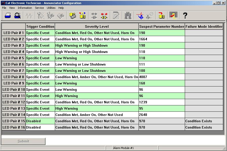
FIGURE 54: CATERPILLAR ® SERVICE TOOL ANNUNCIATOR LED CONFIGURATION SCREEN
DISABLED is used to disable the LED pair. The remaining three parameters will be grayed out when Disabled is selected.
SEVERITY LEVEL
Severity Level defines which types of events the LED pair will react to. Selections that begin with Condition Exists will respond to J1939 Event messages for Failure Mode Identifier (FMI) 31 Condition Exists. For example, LED pair #2 is configured for Condition Exists, Red On, Other Not Used, Horn On with SPN 190 (Emergency Stop Active). This means that when the Annunciator received a J1939 message indicating Emergency Stop with FMI 31, the Red LED will turn on and the Horn will also turn on. Other Not Used indicates that the other LED color in the pair is never used. Green Off (for example) indicates that the green LED lights when the condition chosen for this LED pair is NOT active. Most Severity Level selections imply (a) J1939 Failure Mode Identifier (FMI) code(s): CONDITION EXISTS is equivalent to FMI 31 HIGH WARNING can be FMI 15 or FMI 16 LOW WARNING can be FMI 17 or FMI 18 HIGH SHUTDOWN is equivalent to FMI 0 LOW SHUTDOWN is equivalent to FMI 1 HIGH OR LOW SHUTDOWN is equivalent to FMI 0 or FMI 1


