1 minute read
Discrete I/O Software Configuration


TABLE 11 DISCRETE I/O
INPUTS PIN OUTPUTS PIN OUTPUTS PIN
DIN1 1 NC_1 5 C_6 19 DIN2 11 C_1 6 NO_6 20 DIN3 21 NO_1 7 NC_7 28 DIN4 31 NC_2 15 C_8 29 DIN5 2 C_2 16 NO_7 30 DIN6 12 NO_2 17 NC_8 38 DIN7 22 NC_3 25 C_8 39 DIN8 32 C_3 26 NO_8 40 DIN9 3 NO_3 27 DIN10 13 NC_4 35 DIN11 23 C_4 36 DIN12 33 NO_4 37 GND 4 NC_5 8 GND 14 C_5 9 GND 24 NO_5 10 GND 34 NC_6 18
NO = Normally Open NC = Normally Closed C = Common
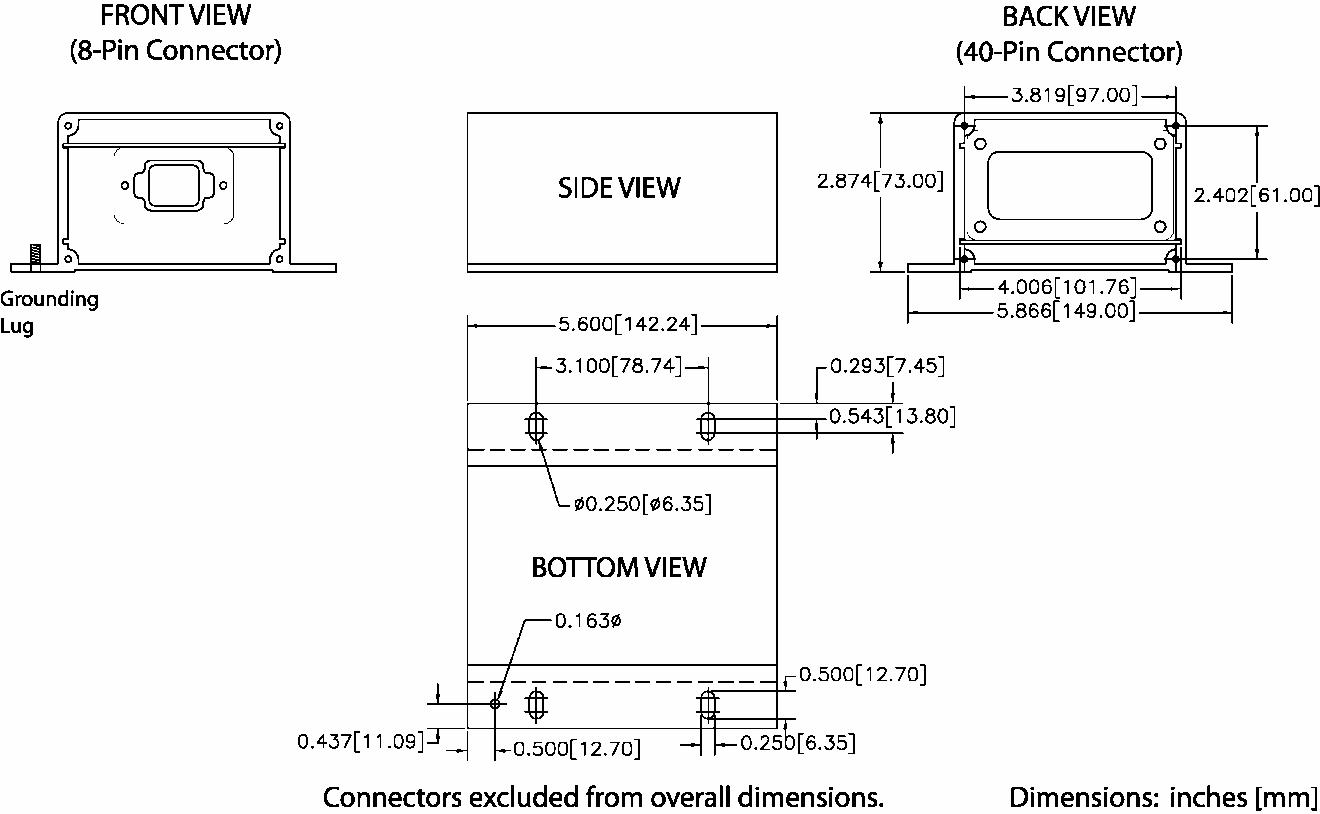
FIGURE 65: THERMOCOUPLE, RTD, AND DISCRETE I/O MODULE PHYSICAL LAYOUT
DISCRETE I/O SOFTWARE CONFIGURATION
The DIO module is field-programmable using the Caterpillar® Service Tool. It is also flash programmable to update software using the Caterpillar® Service Tool. The service tool software must be installed on a Windows PC. The Caterpillar communication adapter must be connected between the PC and the J1939 data link on which the target DIO module is connected. (The service tool may be connected to the EMCP 3 GSC Accessory Data Link service connector).
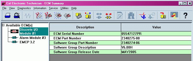
FIGURE 66: CATERPILLAR ® SERVICE TOOL DIO SUMMARY SCREEN
When connecting to the DIO, the user will first see the Module Summary screen shown in FIGURE 66. The service tool configuration tool, accessed by pressing F5 or clicking the configuration tool icon on the toolbar, contains setpoints for configuring the DIO identification, as well as the inputs and outputs.
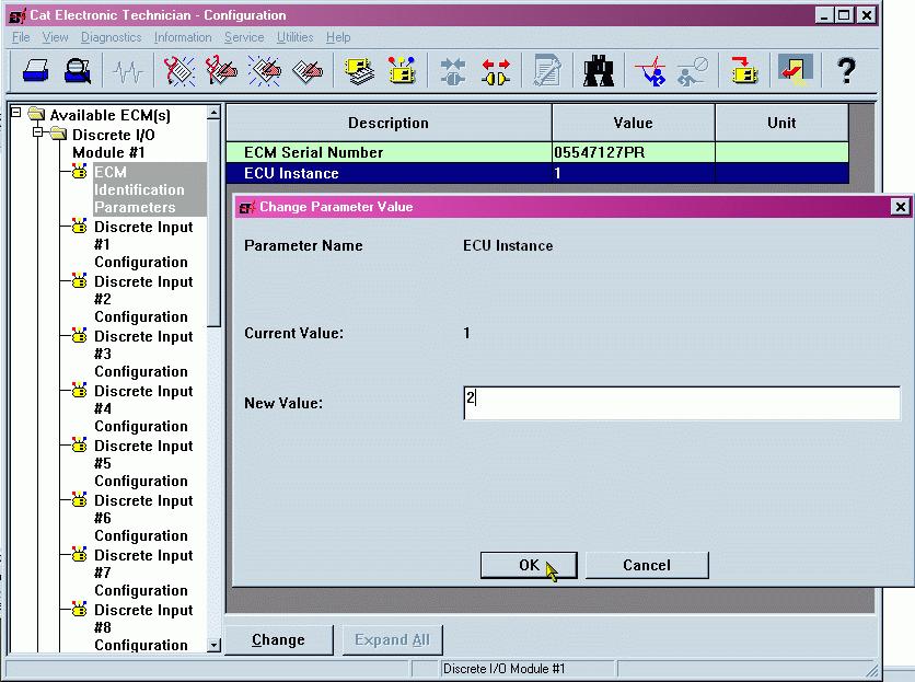
FIGURE 67: CATERPILLAR ® SERVICE TOOL DIO IDENTIFICATION PARAMETERS
FIGURE 67 shows the ECM Identification Parameters list. This list shows the ECM serial number (read-only) of the module that is connected, and allows for configuration of the ECU instance. It is important to match a specific module to a certain ECU Instance. The system will not function properly if ECU instances are duplicated. Upon changing the ECU instance, the Caterpillar


