4 minute read
ECM Replacement option


ECM REPLACEMENT OPTION
To save EMCP 3 GSC configuration data to an ECM Replacement file: Select from the Service Tool menu:
SERVICE > COPY CONFIGURATION > ECM REPLACEMENT
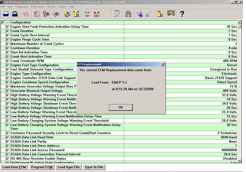
If there are no previously saved field replacement files, the following message is displayed: No Data Is Available. Load From ECM Now. Select which ECM’s configuration data is to be viewed and/or saved for future use. This configuration data to be saved in the ECM Replacement file is shown in FIGURE 43.
NOTE: The option of deselecting certain setpoints can be chosen at this screen.
After any selection changes are completed, the user must choose SAVE TO FILE. The ECM replacement file is now saved for future access. Make sure to note what directory and folder the file is stored at.
FIGURE 43: CATERPILLAR ® SERVICE TOOL ECM REPLACEMENT SCREEN
NOTE: The configuration data must be saved to a file before disconnecting from the service tool or the data WILL BE LOST and must be re-loaded from the source module again.
12.2 LOADING EMCP 3 CONFIGURATION DATA
The loading of EMCP 3 GSC configuration data is very similar between ECM REPLACEMENT and FLEET CONFIGURATION. For illustration purposes, the ECM REPLACEMENT option will be described here.
CONFIGURATION DATA
To load EMCP 3 GSC configuration data from an ECM Replacement file, the user must select from the Service Tool menu: Service > Copy Configuration > ECM Replacement If there exists a previously saved ECM Replacement file, the tool will allow the user to select between them, as shown in FIGURE 44. If there are no previously saved ECM Replacement files, the user must first load configuration data from an EMCP 3 GSC module. For instructions on loading configuration data from an EMCP 3 GSC module, see Chapter 12.1, SAVING EMCP 3 CONFIGURATION DATA.
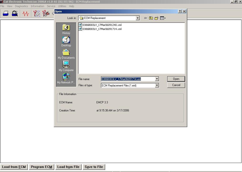
FIGURE 44 : CATERPILLAR ® SERVICE TOOL FIELD REPLACEMENT FILE SELECTION
NOTE: ECM Replacement files are stored in the ECM Replacement folder, while Fleet Configuration files are stored in the Fleet Configuration folder.
The list of setpoints and values are shown after opening an ECM Replacement file.
DESELECTING SETPOINTS
The user has the option of deselecting certain setpoints, if the user wants to keep the values currently configured into the connected EMCP 3 GSC module. The user may upload the selected setpoints into the new EMCP 3 GSC by pressing the PROGRAM ECM button. The user is then prompted with the ECM selector box. The EMCP 3 GSC should be highlighted since it is being programmed. FIGURE 45 below displays the programming of an EMCP 3 GSC with the setpoint values from an ECM Replacement file.
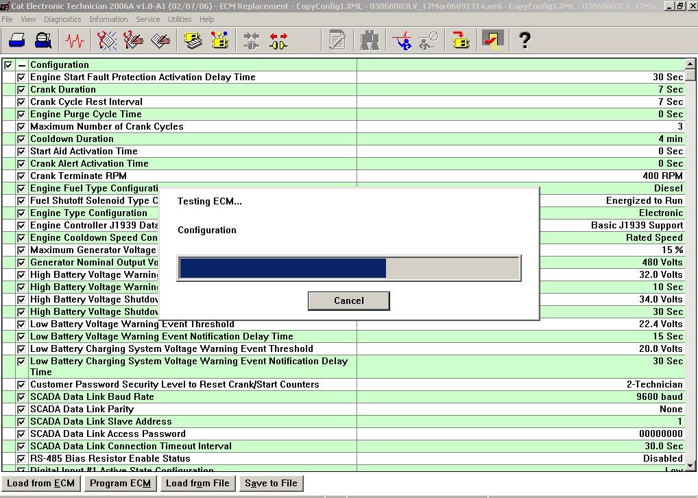
FIGURE 45: CATERPILLAR ® SERVICE TOOL
When the field replacement file has been successfully programmed to the new EMCP 3 GSC, a PROGRAMMING COMPLETE box will display. Press OK. The above steps, for uploading saved configuration data, will need to be repeated for each EMCP 3 GSC module needing same or similar setpoint configurations.
NOTE: When programming EVENT RESPONSE CONFIGURATION setpoints, the control must be in STOP mode. If the control is not in STOP, there will be a message after the programming is complete. The message will show that none of the Event Response Configuration setpoints were changed.
13 PROGRAMMABLE CYCLE TIMER (EMCP 3.2 & 3.3)
The Programmable Cycle Timer (PCT) feature allows the operator to program seven independent times when tasks, called PCT Outputs, will be activated or deactivated automatically during the week. This is useful for cases where two or more generators are required to automatically share the duty of supplying a load throughout the week. Using PCT, each genset can be programmed to start and stop at pre-set times. For example: if a standby set does not have access to a utility supply to power a trickle charger, the PCT can be set for an hour a week to keep the battery well charged.
CAUTION: The co-operation of a transfer switch is required to ensure that the gensets are not stopped on load.
The PCT FEATURE consists of seven independent timers; each timer has the following setpoints (setpoints shown are for PCT #1): PROGRAMMABLE CYCLE TIMER #1: Activation Day of the Week: This permits independent selection of each day (Sun -> Sat) that the timer will activate. PROGRAMMABLE CYCLE TIMER #1: Activation Start Time The time of day (in hours and minutes) that the timer will activate.
PROGRAMMABLE CYCLE TIMER #1: Active Time The duration (in hours and minutes) for which the timer will be active (up to 24 hours). PROGRAMMABLE CYCLE TIMER #1: Output #1 Activation Configuration Whether the Programmable Cycle Timer’s first output will be activated when this timer is active. PROGRAMMABLE CYCLE TIMER #1: Output #2 Activation Configuration Whether the Programmable Cycle Timer’s second output will be activated when this timer is active. The PCT has two internal outputs; these should not be confused with the physical outputs of the control. The outputs are connected internally to the control module. In the standard configuration, PCT OUTPUT #1 is connected to a Remote Initiate command. OUTPUT #2 is connected via DIGITAL SELECTOR #6 to RELAY OUTPUT #8. This effectively allows the operator to configure a timed relay, for external connectivity. The status of the PCTs can be found within the menu structure at:
CONTROL -> PROG CYCLE TIMER -- (See FIGURE 46). The TOP ROW displays the seven PCTs (#1 through #7). The MIDDLE row is for OUTPUT #1. The LAST row is for OUTPUT #2.
13.1 CONTROLLING THE OUTPUTS
The status of each output is indicated by a 1, 0, or - in the PROG CYCLE column under #1 through #7. The number ONE 1 means that this PCT is driving that output to be TRUE


