36 minute read
Programming Using Display........................................................................................................................60 Programming Using Caterpillar® Service Tool


SCROLL DOWN to: ENG COOL TEMP MON
If the setpoint is set to SENSOR then, to change Press ENTER KEY
SCROLL DOWN to: DATA LINK Press ENTER KEY
Press ESCAPE KEY and SCROLL DOWN to: ENG OIL PRES MON
If the setpoint is set to SENSOR then, to change Press ENTER KEY
SCROLL DOWN to: choose DATA LINK, then Press ENTER KEY
PROGRAMMING USING CATERPILLAR® SERVICE TOOL
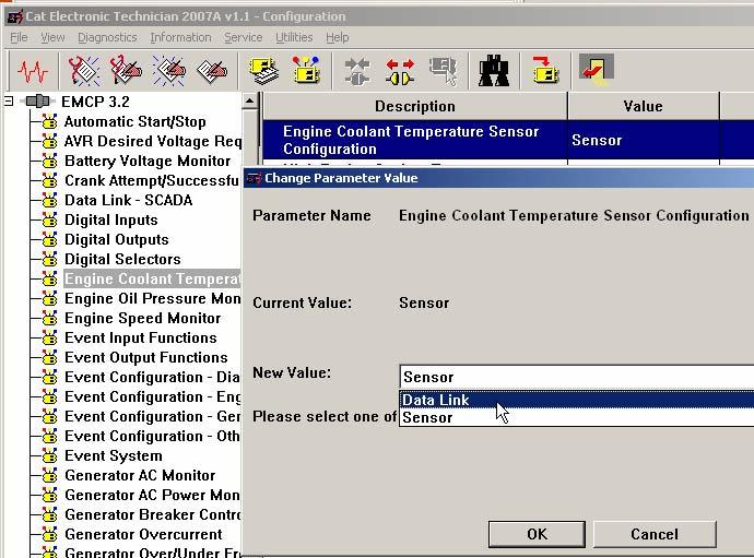
To program the EMCP 3 sensors for Data Link input using the Caterpillar® Service Tool as shown in FIGURE 19, do the following steps: 1. Connect to the EMCP 3 GSC using the Caterpillar® Service Tool 2. Enter the Configuration Tool 3. Select Engine Coolant Temperature Monitor on the left 4. If the Engine Coolant Temperature Sensor Configuration is set to Sensor, change it to Data Link. 5. Select Engine Oil Pressure Monitor on the left 6. If the Engine Oil Pressure Sensor Configuration is set to Sensor, change it to Data Link.
FIGURE 19: SENSOR CONFIGURATION USING CATERPILLAR ® SERVICE TOOL
NOTE: 3500 MUI Generator sets that have EMCP3 GSC software with a release date of Oct. 2006 or earlier are using a flash file that is different from the standard flash file. This flash file has different maps from the standard flash file to support the 3500 MUI engine. From Oct. 2006 released software supports both the standard and the 3500 MUI maps in the one flash file. The map that is used is determined by a setpoint corresponding to each analog input; Oil Pressure Sensor Map Selection Number and Coolant Temperature Sensor Map Selection Number.
9.1 SPARE ANALOG INPUT (EMCP 3.2 & 3.3)
The SPARE ANALOG INPUT has a sensor map in the software for ENGINE OIL TEMPERATURE. This input can be programmed to monitor other parameters such as:
TEMPERATURES
Ambient Air Temperature Engine Oil Temperature Exhaust Temperature Right Exhaust Temperature Left Exhaust Temperature Generator Rear Bearing Temperature
PRESSURES
Air Filter Differential Pressure Fire Extinguisher Pressure Fuel Filter Differential Pressure Oil Filter Differential Pressure Starting Air Pressure
LEVELS
Engine Coolant Level Engine Oil Level Fuel Level External Tank Fuel Level
NOTE: There are 3 sensor maps in the software. Two of the maps are for temperature and the third map is for fuel level. A pressure map is not currently included in the software.
The spare Analog input is capable of reading resistance from 5 ohms up to 2000 ohms. There are three in-built maps to convert from the measured resistance to a value, these are:
1) VDO Oil Temperature Map 2) 3500MUI Oil Temperature Map 3) Fozmula Fuel level Map
Any value below the bottom point on the map or above the highest point on the map will raise a corresponding diagnostic event.
WARNINGS AND SHUTDOWNS
Each of these inputs can be configured to have HIGH WARNINGS, LOW WARNINGS, HIGH SHUTDOWNS and LOW SHUTDOWNS with configurable thresholds. Also, all of the events associated with the analog inputs have programmable time delays. For information on how to program these thresholds and time delays can be found in Chapter 7, Setpoints.
10 OUTPUTS
The EMCP 3 has several outputs that can be configured for different behavior. This chapter defines the outputs and explains how to configure them.
RELAY OUTPUTS
The EMCP 3.1 has six relay outputs and the EMCP 3.2 and 3.3 have eight relay outputs. Each relay is capable of handling 2 A @ 30 V DC. All six relays on the EMCP 3.1 GSC are type-A. The EMCP 3.2 and 3.3 have six relays which are type-A and two relays that are type-C. Note: Type-A relays have one normally-open contact and a common. Type-C relays have one normally-open contact, one normally-closed contact, and a common.
CAUTION: These relays are VOLT FREE meaning that the commons are not referenced to anything within the GSC. The relay contacts are not protected against shorts to battery or ground.
RELAY OUTPUT #1 is dedicated to control the starter motor on MUI engines. On EUI engines, this relay may or may not be connected. RELAY OUTPUT #2 is dedicated to enable fuel on MUI engines. On EUI engines, this relay may or may not be connected. Consult your Genset package manuals. The six remaining Relay Outputs on the EMCP 3.2 and EMCP 3.3 (four remaining Relay Outputs on EMCP 3.1) are programmable for various other applications.
DIGITAL OUTPUTS
The EMCP 3.1 does not have any digital outputs. The EMCP 3.2 has one digital output, and the EMCP 3.3 has two digital outputs. Each output is a discrete 300 mA sinking driver output. These outputs are programmable for various applications.
DIGITAL SELECTORS
Relay outputs #3 and higher as well as digital outputs (on EMCP 3.2 and 3.3) are programmable and can be set to operate based on different conditions. In order to select which condition controls the output, there are functions called DIGITAL SELECTORS associated with each relay output (#3 and higher) and digital output. This is shown in FIGURE 20, FIGURE 21, and FIGURE 22. • EMCP 3.1 has four (4) Digital Selectors (connected to Relay Outputs 3-6) • EMCP 3.2 has seven (7) Digital Selectors (connected to Relay Outputs 3-8 and Digital Output 1) • EMCP 3.3 has eight (8) Digital Selectors (connected to Relay Outputs 3-8 and Digital Outputs 1-2) The Digital Selector software acts like a 12 position switch for each relay and is used to determine which one of those conditions will actually be associated with each output. For each output there are 10 different options of conditions that can make the output go ACTIVE, one option that will allow the output to be controlled with a SCADA data link command, and one condition to DISABLE the output altogether. These options are shown in FIGURE 20, FIGURE 21, and FIGURE 22. Definitions for these options are in Chapter 10.1, Digital Selector Options.
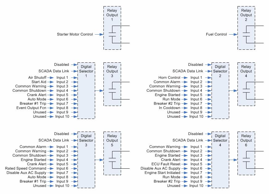
FIGURE 20 EMCP 3.1 OUTPUTS
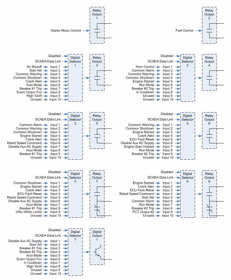
FIGURE 21 EMCP 3.2 OUTPUTS
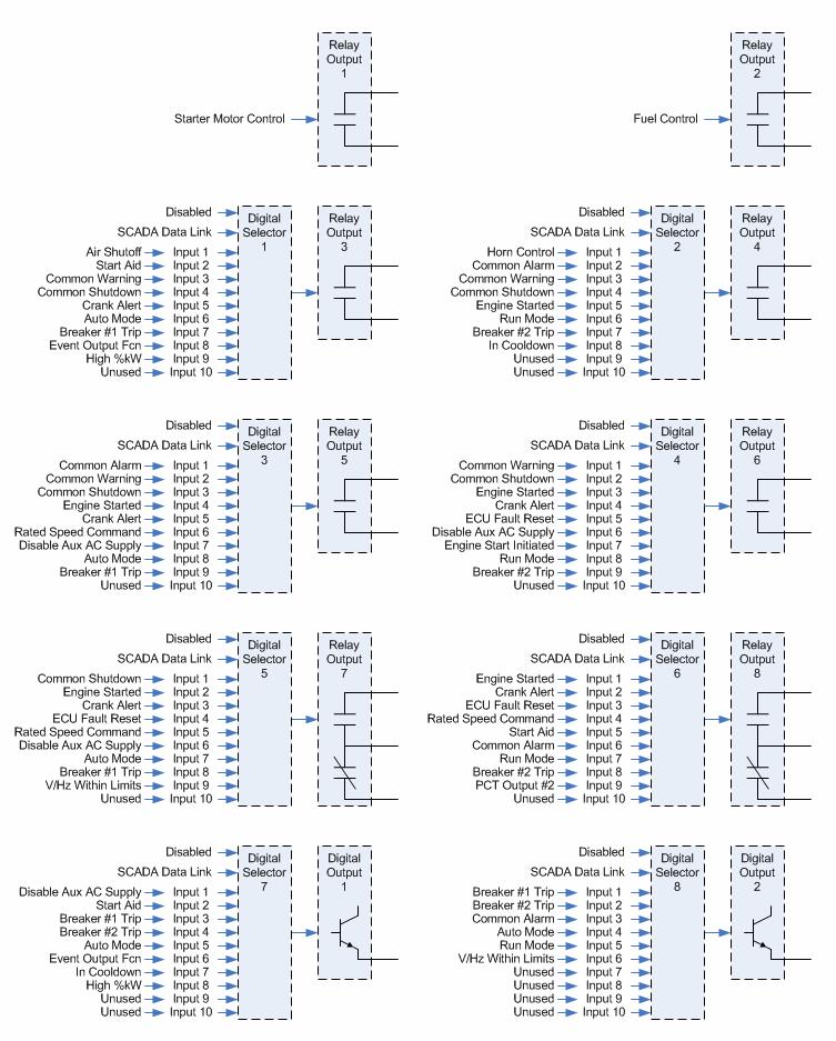
FIGURE 22 EMCP 3.3 OUTPUTS
10.1 DIGITAL SELECTOR OPTIONS
The digital selector is a software function that acts like a 12 position switch, to determine the behavior of an output. For each selector there are 10 unique conditions that can make the output go active, an option to control the output via the SCADA data link, and one option to disable the output altogether. The 10 unique conditions for each selector are shown in FIGURE 20, FIGURE 21, and FIGURE 22 above. The Disabled option causes the output to stay Inactive. Inactive for the relay outputs means that the Normally Open relay contacts will remain open. Inactive behavior for the digital outputs is determined by the Active State Configuration setpoint. For more information on Setpoints and Configuring Outputs see the following Chapters; 10.2, Programming Outputs Using The Service Tool and 10.3, Programming Outputs Using The Display. The SCADA Data Link option allows outputs to be activated by commands sent via the Modbus (SCADA) Data Link. These commands are sent via registers 628 through 636. For more information, refer to Chapter 21.3, Discrete Inputs and Outputs.
DEFINITIONS OF DIGITAL SELECTOR OPTIONS
As shown in FIGURE 20, FIGURE 21, and FIGURE 22, the Digital Selectors can be configured to be driven by one of the following conditions (all conditions not available on all Digital Selectors):
AIR SHUTOFF
Activated by Emergency Stop condition
Activated by Overspeed condition
Automatically deactivates after 15 second delay
AUTO MODE
Activated after the Auto Key has been pressed (or a Modbus command is given to set
Engine Operating Mode to Auto - register 302) and while the EMCP 3 GSC remains in the
Auto mode
BREAKER #1 TRIP
Activated when any event occurs that has an event response configuration set for breaker trip 1. See Chapter 5.1, Configuring Event Responses for more information.
Deactivates when the event is neither present nor active.
NOTE: This output does not control a circuit breaker unless the user makes the connections to do so.
BREAKER #2 TRIP
Activated when any event occurs that has an event response configuration set for breaker trip 2. See section Chapter 5.1, Configuring Event Responses for more information.
Deactivates when the event is neither present nor active
NOTE: This output does not control a circuit breaker unless the user makes the connections to do so.
COMMON ALARM
Activated anytime the EMCP 3 GSC has a present or active warning or shutdown event in the event system.
Deactivates when no warnings or shutdowns are present or active
COMMON WARNING
Activated anytime the EMCP 3 GSC has a present or active warning event in the event system.
Deactivates when no warnings are present or active.
COMMON SHUTDOWN
Activated anytime the EMCP 3 GSC has a present or active shutdown event in the event system.
Deactivates when no shutdowns are present or active
CRANK ALERT
Requires setpoint Crank Alert Activation Time set greater than zero
Activated when engine start is initiated, before engine begins to crank
Deactivates after Crank Alert Activation Timer expires
DISABLE AUX AC SUPPLY
Intended to be used to disconnect the battery charger, heaters etc when the engine is running
Activated when engine start is initiated
Deactivates when engine is stopped: RPM=0
ECU FAULT RESET
For electronic engines that do not support J1939 communication.
When Reset Engine Events is selected in the Event logs, it will activate for one second and then deactivate. This option is only available when the engine is set to Electronic and the communication is set to No J1939 communication.
ENGINE START INITIATED
Activated when engine start is initiated (engine is going to start, even when engine speed is still 0)
Deactivates when engine stop is initiated (engine is going to stop, even when engine speed is still at rated speed)
ENGINE STARTED
Activated when engine has reached crank terminate speed
Deactivates when engine is stopped: RPM=0
EVENT OUTPUT FUNCTION
Requires setpoint configuration for Event Output Function #1
Activated while the event(s) configured for Event Output Function #1 is (are) active
For more information on configuring and using the Event Output Function, see
Programming Event Output Functions in Chapters; 10.2, Programming Outputs Using The
Service Tool and 10.3, Programming Outputs Using The Display below.
HIGH %KW
Activated when Programmable Trip Point #1 is active. Programmable Trip Point #1 activates based on high %kW, according to user-configurable thresholds. For more information on configuring the Programmable Trip Point function, see Chapter 15,
Programmable Trip Point function.
HORN CONTROL
Activated when any event occurs that has an event response configuration set for audible alert
Deactivates when event is neither present or active or when the alarm acknowledge key is pressed
IN COOLDOWN
Requires setpoint Cooldown Duration set greater than zero
Activated when engine stop has been initiated and cooldown cycle begins
Deactivates when cooldown timer has expired and remains deactivated any time the genset is not in cooldown
PCT OUTPUT #2
Activated any time Output #2 of the Programmable Cycle Timer is Active
For more information on configuring Programmable Cycle Timers, see Chapter 13,
Programmable Cycle Timer.
RATED SPEED COMMAND
Activated when Rated Speed is commanded. Will always be active unless Idle Speed is commanded.
NOTE: Intended to give a rated speed permissive signal to a governor
RUN MODE
Activated after the Run Key has been pressed (or a Modbus command is given to set
Engine Operating Mode to Run - register 302) and while the EMCP 3 GSC remains in the
Run mode.
START AID
Requires setpoint Start Aid Activation Time set greater than zero
Activated when engine start is initiated before the engine begins to crank
Deactivates after Start Aid Activation Timer expires
V & HZ WITHIN LIMITS
Activated when measured generator voltage and frequency are both within the Warning thresholds for their respective parameters
Deactivates when either measured generator voltage or frequency are outside of the
Warning thresholds for their respective parameters
10.2 PROGRAMMING OUTPUTS USING THE SERVICE TOOL
Outputs can be configured by using the Caterpillar® Service Tool. To begin, connect to the EMCP 3 GSC and select Service > Configuration from the menu to enter the Configuration Tool,
FIGURE 23.
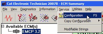
FIGURE 23 SELECTING CONFIGURATION
The following sections will explain the steps involved in configuring an output, and walk through an example of configuring Relay Output 3 to Breaker #1 Trip and Digital Output 1 to Event Output Function on the EMCP 3.2. The steps are identical for EMCP 3.1 and 3.3 (Digital Output 1 doesn’t apply to the 3.1).
NOTE: Some setpoint values may be different from the screenshots; those may not be important to this example. However, be aware that changing other setpoints will cause the EMCP 3 to behave differently, so any changes should be done carefully. As always, it is recommended to save a setpoint configuration file before making any changes as shown in Chapter 12, Saving and Restoring Setpoints.
PROGRAMMING DIGITAL SELECTORS
To program a Digital Selector, select Digital Selectors from the left pane. Edit the Digital Selector Source Configuration for the appropriate Digital Selector. The options given are Disabled, Data Link, and Input #1 through Input #10. Refer to in FIGURE 20, FIGURE 21, and FIGURE 22 to determine which input corresponds to which option. The EMCP 3.2 has seven (7) Digital Selectors. As the screenshot shows FIGURE 24, more are listed, but are given as Disabled or Not Installed. This means they don’t apply to the EMCP 3.2.
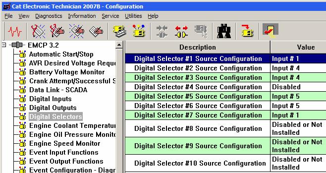
FIGURE 24 SELECTING DIGITAL SELECTOR
To configure Relay Output 3 to Breaker #1 Trip, the corresponding Digital Selector must be configured. Referring back to FIGURE 21, note that Digital Selector 1 is tied to Relay Output 3. Breaker #1 Trip is Input 7. Modify Digital Selector #1 Source Configuration, selecting Input #7, Figure 25.
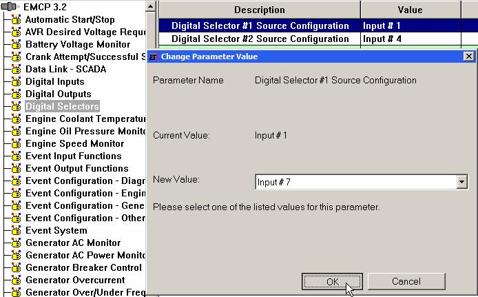
FIGURE 25 SELECTING INPUT #7
Similarly, note that Digital Selector #7 is tied to Digital Output 1, and Event Output Function is Input 6. So modify Digital Selector #7 Source Configuration, selecting Input #6. The resulting settings are shown below, FIGURE 26.

FIGURE 26 SELECTOR #7 RESULTS
PROGRAMMING EVENT OUTPUT FUNCTIONS
If it is desired to trigger an output based on an event or a set of events, then an additional step is required after one of the Digital Selectors is configured for Event Output Function (as was done for Digital Selector 7 in the example above). This is to define the type of event(s) that will activate the output. The EMCP 3.2 only has one (1) Event Output Function. Two setpoints define the Event Output Function. EVENT OUTPUT FUNCTION #1 SUSPECT PARAMETER NUMBER: Every event in the EMCP 3 system is defined with an SPN and FMI. This is the SPN. The Caterpillar® Service Tool shows the parameter list, allowing any one to be selected. The SPN selected here does not matter if it is used to drive the output based on a general type of event such as warnings, shutdowns, etc. EVENT OUTPUT FUNCTION #1 TRIGGER CONDITION: This setpoint defines the FMI (Failure Mode Identifier) or set of FMIs that will trigger the output. It is also used to determine whether the output should be driven only by an event with a specific SPN (called a Specific Event), or any SPN that has a certain FMI (called a General Event). The General Event options are meant for special cases. If it is used to drive an output based on any warning or shutdown, it is recommended to configure a Digital Selector to Common Warning, Common Shutdown, or Common Alarm, instead of using the General Event options. EXAMPLE 1: Configuring the Event Output Function for any fault related to the Accessory Data Link. Set Event Output Function #1 Suspect Parameter Number to Accessory Data Link, and set Event Output Function #1 Trigger Condition to Specific Event - Any Warning, Shutdown, or Diagnostic, FIGURE 27 . Figure 27 Configuring the Event Output Function EXAMPLE 2: Configuring the Event Output Function for Custom Event #1 Condition Exists (for example, if using the Custom Event from Event Input Function #1). Set Event Output Function #1 Suspect Parameter Number to Custom Event #1 (the number matches with the Event Input Function number), and set Event Output Function #1 Trigger Condition to Specific Event - Condition Exists, FIGURE 28.
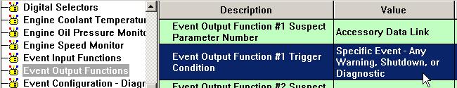
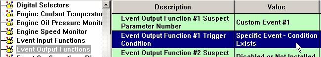
FIGURE 28 SPECIFIC EVENT
PROGRAMMING RELAY OUTPUTS
Relay Outputs 1-6 are Form-A relays, which means they only have Normally Open contacts. The polarity of these relays are not configurable. They are viewable on the Caterpillar® Service Tool, by selecting Relay Outputs in the left pane. All of the outputs are configured with an active state of High, indicating that the contacts are closed when the condition is active (indicating that the relays behave as Normally Open relays), Figure 29.
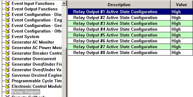
FIGURE 29 RELAY OUTPUTS
NOTE: Read-only setpoints do not look different from other setpoints on the Caterpillar® Service Tool. However, if the setpoint is modified, the Service Tool will return an error, as shown below in the following set of screenshots, FIGURES 30, 31, and 32.
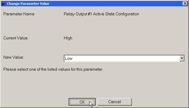
FIGURE 30 READ-ONLY SETPOINT ERROR
FIGURE 31 READ-ONLY SETPOINT ERROR
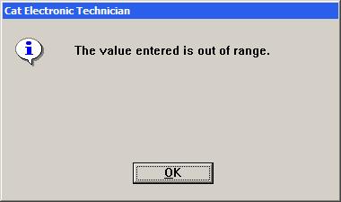
FIGURE 32 READ-ONLY SETPOINT ERROR
Relay Outputs 7 and 8 (available on 3.2 and 3.3) are Form-C relays, which means that both Normally Open and Normally Closed contacts are available. Changing the polarity involves rewiring to the opposite pin. The pins for Relay Outputs 7 and 8 are listed here.
EMCP 3 70-PIN AMP CONNECTOR
Pin # Function
1 Relay 8 Normally Open (NO) Contact 2 Relay 7 Normally Open (NO) Contact 14 Relay 8 Normally Closed (NC) Contact 15 Relay 7 Normally Closed (NC) Contact 24 Relay 8 Common 25 Relay 7 Common
For more wiring details, see Figure 2 and Figure 3 in Chapter 3.7, EMCP 3.1, 3.2, 3.3 Electrical Diagrams.
PROGRAMMING DIGITAL OUTPUTS (EMCP 3.2 AND 3.3)
Digital Outputs have a sinking driver output. When the condition controlling the output becomes active, the default setting of High for the Digital Output Active State Configuration causes the output to be pulled to battery negative voltage. This will turn on a circuit that is wired between the output and battery voltage. When the condition controlling the output is inactive, the default setting of High for the Digital Output Active State Configuration causes the output to be floating. This will turn off the circuit that is wired between the output and battery voltage. To reverse this polarity (i.e. turn on a circuit when the controlling condition is inactive), select Digital Outputs from the left pane and change the Active State Configuration for the desired output to Low, FIGURE 33.
FIGURE 33 ACTIVE STATE CONFIGURATION
10.3 PROGRAMMING OUTPUTS USING THE DISPLAY
Outputs can be configured by using the EMCP 3 display. For some of the setpoints, LEVEL 2 ACCESS is required. For information on obtaining Level 2 Access refer to Chapter 6, Security. This section will assume that Level 2 Access has already been obtained. The following explains the steps involved in configuring an output, and includes a walk through example for configuring Relay Output 3 to Breaker #1 Trip and Digital Output 1 to Event Output Function on the EMCP 3.2. The steps are identical for EMCP 3.1 and 3.3 (except Digital Output 1 doesn’t apply to the 3.1) although the screens may look slightly different.
PROGRAMMING DIGITAL SELECTORS
To program the Digital Selectors, go through the following menu options.
MAIN MENU

scroll down to:
CONFIGURE
enter key MAIN MENU AC OVERVIEW CONFIGURE
scroll down to:
Setpoints
enter key CONFIGURE SECURITY SETPOINTS
scroll down to:
OTHER
enter key SETPOINTS NETWORK OTHER
DIGITAL SELECTORS
enter key

enter key to configure Digital Selector #1 to edit the Source Configuration. The options are enter key Disabled, Use Input #1 (through #10), and finally Data Link. Refer to Figure 20, Figure 21, and Figure 22 to determine which input corresponds to which option. In order to configure Relay Output 3 to Breaker #1 Trip, the corresponding Digital Selector must be configured. Referring back to Figure 21, note that Digital Selector 1 is tied to Relay Output 3. Breaker #1 Trip is Input 7. So
scroll down to:
USE INPUT #7

to select Use Input #7.
enter key
Similarly, note that Digital Selector #7 is tied to Digital Output 1, and Event Output Function is Input 6.
ESCAPE KEY to return to the list of Digital Selectors
scroll down to:
DIGITAL SELECTOR #7
enter key

enter key to edit the Source Configuration.
SCROLL DOWN TO:
USE INPUT #6
enter key

PROGRAMMING EVENT OUTPUT FUNCTIONS
If it is desired to trigger an output based on an event or a set of events, then an additional step is required after one of the Digital Selectors is configured for Event Output Function (as was done for Digital Selector 7 in the example above). This is to define the type of event(s) that will activate the output. TO PROGRAM EVENT OUTPUT FUNCTIONS, go through the following menu options:
MAIN MENU
scroll down to:
CONFIGURE
ENTER KEY
scroll down to:
SETPOINTS
enter key
scroll down to:
EVENTS
scroll down to:
EVENT O/P FUNCTIONS
ENTER KEY
to edit
EVENT OUTPUT FUNCTION #1
ENTER KEY MAIN MENU AC OVERVIEW CONFIGURE
CONFIGURE SECURITY SETPOINTS


The EMCP 3.2 only has one (1) Event Output Function. Two setpoints define the Event Output Function. EVENT OUTPUT FUNCTION #1 TRIGGER CONDITION: This setpoint defines the FMI or set of FMIs that will trigger the output. It is also used to determine whether the output should be driven only by an event with a specific SPN (called a Specific Event), or any SPN that has a certain FMI (called a General Event). The General Event options are only intended for special cases. If it is desired to drive an output based on any warning or shutdown, it is recommended to configure a Digital Selector to Common Warning, Common Shutdown, or Common Alarm, instead of using the General Event options. EVENT OUTPUT FUNCTION #1 SUSPECT PARAMETER NUMBER: Every event in the EMCP 3 system is defined with an SPN and FMI. This is the SPN. The Caterpillar® Service Tool shows the parameter list, allowing any one to be selected. If it is desired to drive the output based on a general type of event (for example, any warning, any shutdown, etc), then the SPN selected here does not matter.
EXAMPLE 1: Configuring the Event Output Function for any fault related to the Accessory Data Link. Set Event Output Function #1 Suspect Parameter Number to Accessory Data Link, and set Event Output Function #1 Trigger Condition to Specific Event - Any Warning, Shutdown, or Diagnostic.
to edit
TRIGGER CONDITION
ENTER KEY
.

Scroll Up or Scroll Down until Specific Event - Any Warning, Shutdown, or Diagnostic is shown (an abbreviated text is shown due to space limitations).
ENTER KEY

EXAMPLE 2: Configuring the Event Output Function for Custom Event #1 Condition Exists (for example, if using the Custom Event from Event Input Function #1). Set Event Output Function #1 Suspect Parameter Number to Custom Event #1 (the number matches with the Event Input Function number), and set Event Output Function #1 Trigger Condition to Specific Event - Condition Exists (this options reads CONDITION EXISTS on the EMCP 3.1 or 3.2 display, and SPC CONDITION EXISTS on the EMCP 3.3 display).
PROGRAMMING RELAY OUTPUTS
Relay Outputs 1-6 are Form-A relays, which means they only have Normally Open contacts. The polarity of these relays are not configurable. They are viewable on the display by going through the following menu options:
MAIN MENU
scroll down to:
CONFIGURE
enter key MAIN MENU AC OVERVIEW CONFIGURE
scroll down to:
Setpoints
enter key CONFIGURE SECURITY SETPOINTS
scroll down to:
I/O
ENTER KEY
scroll down to:
RELAY OUTPUTS
ENTER KEY
Select any of the outputs
ENTER KEY

All of the outputs are configured with an active state of High, indicating that the contacts are closed when the condition is active (indicating that the relays behave as Normally Open relays).
NOTE: The lock icon with no number after it indicates that the setpoint can not be changed from the display.
Relay Outputs 7 and 8 (available on 3.2 and 3.3) are Form-C relays, which means that both Normally Open and Normally Closed contacts are available. Changing the polarity involves rewiring to the opposite pin. The pins for Relay Outputs 7 and 8 are listed here. For more wiring details, see Figure 2 and Figure 3 in Chapter 3.7, EMCP 3.1, 3.2, 3.3 Electrical Diagrams.
EMCP 3 70-PIN AMP CONNECTOR
Pin # Function
1 Relay 8 Normally Open (NO) Contact 2 Relay 7 Normally Open (NO) Contact 14 Relay 8 Normally Closed (NC) Contact 15 Relay 7 Normally Closed (NC) Contact 24 Relay 8 Common 25 Relay 7 Common
PROGRAMMING DIGITAL OUTPUTS (EMCP 3.2 AND 3.3)
Digital Outputs have a sinking driver output. When the condition controlling the output becomes active, the default setting of High for the Digital Output Active State Configuration causes the output to be pulled to battery negative voltage. This will turn on a circuit that is wired between the output and battery voltage. When the condition controlling the output is inactive, the default setting of High for the Digital Output Active State Configuration causes the output to be floating. This will turn off the circuit that is wired between the output and battery voltage. To reverse this state (i.e. turn on a circuit when the controlling condition is inactive), go through the following menu options:
MAIN MENU
scroll down to:
CONFIGURE
enter key
scroll down to:
Setpoints
enter key MAIN MENU AC OVERVIEW CONFIGURE
CONFIGURE SECURITY SETPOINTS
to edit scroll down to:
I/O
ENTER KEY
scroll down to:
DIGITAL OUTPUTS
ENTER KEY
DIGITAL OUTPUT #1 ENTER KEY

EMCP 3.2 (or scroll down to select Digital Output #2, EMCP 3.3 only)
EMCP 3.3

to edit
ACTIVE STATE CONFIGURATION
to select
ENTER KEY
LOW
scroll up
ENTER KEY


11 MODIFIABLE TEXT STRINGS
The EMCP 3 GSC supports the customization of event names in the event log. This feature
called MODIFIABLE TEXT STRINGS. The MODIFIABLE TEXT STRINGS feature uses events called CUSTOM EVENTS. These are special events that can be configured to display a custom text string in the event log, which is useful when an existing SPN and text string does not exist for the required event. These events can be configured and triggered similar to other events. However, these events are unique in that their displayed text strings can be customized via the Caterpillar® Service Tool using any character in the supported character set of the EMCP 3 GSC software flash file. Furthermore, the Caterpillar® Service Tool has the capability to upload a Modifiable Text Strings configuration file (containing previously saved custom event text strings) from the computer, or download a configuration from the EMCP 3 GSC to the computer. In order to display a custom text string for an event, following steps must be taken: 1. One of the Event Input Functions must be configured with a Suspect Parameter Number (SPN) of Custom Event and a Failure Mode Identifier (SPN) of Status (or Condition Exists). For more information on configuring Event Input Functions, see Chapter 8.1. 2. A custom string must be entered, using the Modifiable Text Strings tool in the Caterpillar® Service Tool, as described in Chapter 11.2. 3. The language must be set to the customer language, not to Technician English. An example of the modifiable text strings is given below. FIGURE 34 shows the setting within the Caterpillar® Service Tool that customizes the text description of Custom Event #1. FIGURE 35 shows the event log view of the event when it has become present, as viewed in Technician English. FIGURE 36 shows the same as above, viewed in the secondary language (in this case, English).
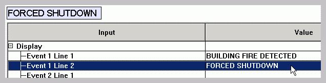
FIGURE 34 : CUSTOMIZING A TEXT STRING IN CATERPILLAR ® SERVICE TOOL


FIGURE 35 : BEFORE CUSTOMIZING THE TEXT STRING FIGURE 36: AFTER CUSTOMIZING THE TEXT STRING
The Modifiable Text Strings functionality differs between EMCP 3 GSC platforms and language sets. The EMCP 3.1 supports up to six Custom Events; the EMCP 3.2 and 3.3 support up to eight Custom Events. Because of their differences in screen resolution, the display platforms also differ in the number of pixels allowed (characters vary in width) in the custom event name. Different language sets support a different set of characters. Due to all of these differences, Modifiable Text String configuration files have limited portability between EMCP 3 GSC modules.
11.1 LANGUAGE SUPPORT
The primary language for the EMCP 3 GSC control will always be U.S. (Technician) English. The user will always be able to revert back to Technician English from the selected language that is supported by the flash file. However, when the EMCP 3 GSC display is viewed in Technician English, the user will not be able to view the custom text strings and will only be able to view the default strings (as in FIGURE 35) for a given input. The EMCP 3 GSC has the capability of supporting one flash file containing one secondary language at any particular time. If the user is interested in having a new secondary language, a new flash file to configure the new language must be installed. Therefore, the user will not be allowed to install multiple flash files supporting different languages. The EMCP 3 GSC supports Unicode characters from the English character set, as well as the character set from the local language supported by the file. It is the user’s responsibility to install the preferred flash file with the correct language support that will allow the modification of text strings. The user is also responsible for choosing the appropriate operating system or Unicode text entry system for the chosen language. The Caterpillar® Service Tool software accepts input from the PC keyboard settings. If, for example, the PC keyboard setting is for U.S. English, it may be difficult to enter Russian (or other non-English) characters.
11.2 MODIFIABLE TEXT STRING CONFIGURATION FILE
The user will have the capability of transferring the custom text string data to and from the EMCP 3 GSC by means of the Caterpillar® Service Tool, and the capability of modifying the configuration file offline. When not connected to the Caterpillar® Service Tool, the user has the ability to make changes to a saved configuration file by navigating to the menu File > Open > Modifiable String Data File, as shown in the FIGURE 37 below.
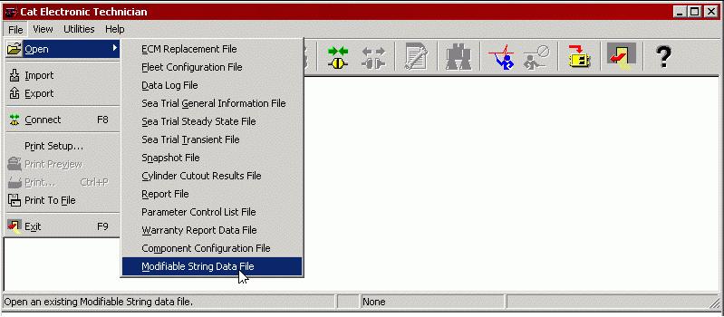
FIGURE 37: CATERPILLAR SERVICE TOOL EMCP 3 GSC OFFLINE EDITING
The user is prompted to select a previously saved file in XML format, to edit, as shown in
FIGURE 38.
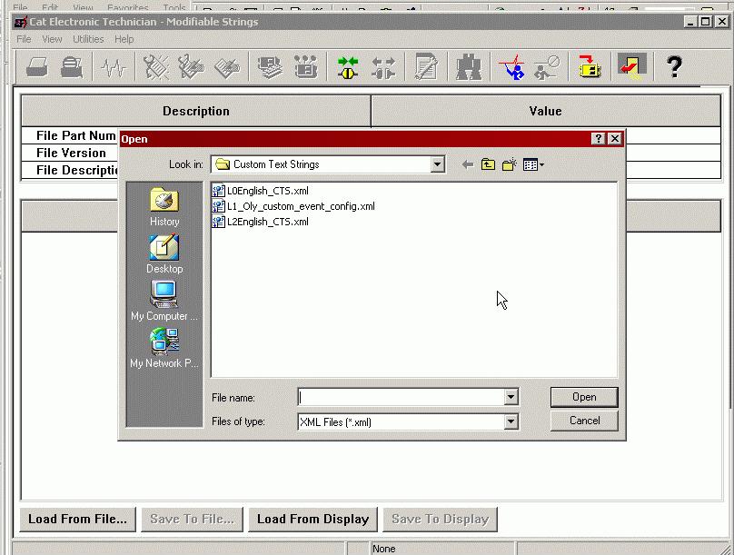
FIGURE 38 : CATERPILLAR ® SERVICE TOOL EMCP 3 GSC OFFLINE CONFIGURATION FILE SELECTION
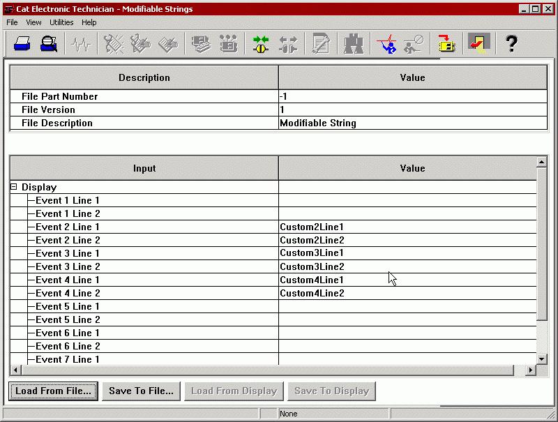
FIGURE 39 : CATERPILLAR ® SERVICE TOOL EMCP 3 GSC OFFLINE CONFIGURATION FILE EDITING
NOTE: The user must Save any offline changes before attempting to connect the Service Tool to the EMCP 3 GSC, or the changes will not be saved as shown in FIGURE 39.
Besides Offline Editing, the user will have the capability of uploading and downloading a configuration data when Online. The configuration file (same file for offline or online editing) includes but is not limited to, the following data: • The language ID • Configurable parameter value name current strings • List of Unicode characters that the EMCP 3 GSC supports • Pixel Width of each Unicode character
11.3 PROGRAMMING MODIFIABLE TEXT STRINGS USING CATERPILLAR® SERVICE TOOL
The Modifiable Text Strings are programmable via the Caterpillar® Service Tool, version 2005B v2.0 or later.
In order to update or change the Modifiable Text String values, the following menu options are accessible via the Caterpillar’s Service Tool, keeping in mind that the Modifiable Text String parameters can ONLY be updated when the EMCP 3 GSC is in the STOP position. After connecting to the EMCP 3 GSC, navigate to the menu Service > Modifiable Strings.
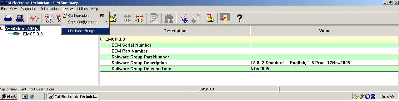
FIGURE 40 : CATERPILLAR ® SERVICE TOOL EMCP 3 GSC SUMMARY SCREEN
There are two options accessible from the Modifiable String screen (Load from ECM and Load from File). The user must select one of the options before editing the Modifiable Text Strings. Considering that the option of programming Modifiable Text String is usually completed upon initial setup, the user should access the Load from ECM option. The service tool is now collecting information from the control and will display the following message: Loading Data From ECM. After the downloading of data from the EMCP 3 GSC to the service tool, the user is now able to enter the modifiable text strings. The Modifiable Text String are considered a pair, and the user has the option of customizing the pair of text strings. Therefore, the user is allowed to enter two lines of Custom Text as displayed in the figure below. The user is able to save the entered custom text strings and has the option of saving the Custom text strings to the display or a file.
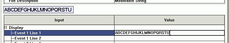
FIGURE 41: ENTERING A STRING IN THE CATERPILLAR ® SERVICE TOOL MODIFIABLE TEXT STRING SCREEN
The lavender box at the left near the top of the service tool Modifiable Strings screen shows the entered text in the final font and character spacing, and indicates how much space is remaining on the EMCP 3 GSC display line. The second line has less available space, because the event log index is also displayed on that line (see FIGURE 41).
NOTE: The Modifiable Text String parameter value’s field is initially blank until it is replaced with a custom text string parameter value. The custom text string parameter value entered will replace the default strings.
Remember only when you Save To ECM will the changes made be uploaded to the EMCP 3 GSC and take effect. Then the EMCP 3 GSC will display the custom text string parameter value(s) in the flash file secondary language. The user’s custom text string parameter(s) are displayed only when an event FMI 31 for the custom event is triggered. When viewing the display in Technician English, the user will only have access to the Default Strings. Since the Modifiable Text Strings are offered as a string pair, the default strings will be displayed as Custom Event #1 on the first line, and Status on the second line. The user’s Custom Text Strings are displayed in the user’s preferred language. If the service tool doesn’t support the user’s preferred language, US English will be used.
11.4 TROUBLESHOOTING MODIFIABLE TEXT STRINGS
The following are a common problems with Modifiable Text String and the steps you can take to resolve them.
PROBLEM: I AM UNABLE TO VIEW THE CUSTOM EVENT AT ALL
TEST STEP 1. CHECK FOR WIRING PROBLEMS.
From the Main Menu, select I/O Status. When you activate the input, does the appropriate input indication change? If not, check your wiring. The input should be wired between the appropriate digital input pin and ground (-BATT).
EXPECTED RESULT:
When you flip the switch that is wired between the proper input pin and (-BATT), the I/O Status screen indication changes from a hyphen (-) to a number (depending on which number input you are switching).
RESULTS:
OK - The wiring and indication on the EMCP 3 GSC are okay. Proceed to Test Step 2. NOT OK - The wiring needs correction. Stop and repair.
TEST STEP 2. IS THE EVENT INPUT FUNCTION CONFIGURED FOR THE CUSTOM EVENT?
In order to show the custom text string in the event log, the EVENT INPUT FUNCTION #X SUSPECT PARAMETER NUMBER must be configured for a special type of event called CUSTOM EVENT, and
the FAILURE MODE IDENTIFIER must be set to CONDITION EXISTS. Be aware of a numbering offset. Digital Input #3 triggers Event Input Function #1, which (if configured properly) triggers Custom Event #1. For higher numbered Digital Inputs, the numbers increase correspondingly.
EXPECTED RESULT:
The Event Input Function #1 Suspect Parameter Number (if using Digital Input #3) is configured for Custom Event, and the Event Input Function #3 Failure Mode Identifier is configured for Condition Exists (called Status on the Service Tool)
RESULTS:
OK - The setpoints are configured correctly. Proceed to Test Step 3.
NOT OK - The setpoints need to be changed. You need either security level 2 access, or access to the Service Tool, to change these setpoints. If changing the Suspect Parameter Number setpoint from the control panel display, first the category Others must be selected, and then Custom Event (the items are not in alphabetical order).
TEST STEP 3. IS THE EVENT RESPONSE ENABLED?
Each type of event, such as Custom Event #1 Condition Exists, has an associated Event Response Configuration, which must be enabled for the event to show up in the event log.
EXPECTED RESULT:
Custom Event #n Condition Exists Event Response Configuration (the setpoint name may or may not include the words Condition Exists) for the particular custom event you are trying to trigger, should be set to Warning, Soft Shutdown, Hard Shutdown or Active Only (other settings are optional).
RESULTS:
OK - The setpoint is already configured for one of those (warning, soft shutdown, hard shutdown or Active Only). Please, call your customer support representative for further assistance. NOT OK - The setpoint needs to be changed. You need either security level 2 access, or access to the Service Tool, to change this setpoint. Make sure the ECS is set to STOP before attempting to change this setpoint.
PROBLEM: THE CUSTOM EVENT IS VIEWABLE BUT, THE DEFAULT TEXT IS SHOWN ON THE EMCP 3 GSC DISPLAY INSTEAD OF THE USER’S CUSTOM STRING
TEST STEP 1. VERIFY THAT THE CONTROL PANEL DISPLAY IS SET TO THE PRIMARY LANGUAGE.
The control panel display supports a user language (which may be English, or perhaps a different language) as well TECHNICIAN ENGLISH. If your primary language is English, you may not notice that the display is set to TECHNICIAN ENGLISH.
NOTE: User language of ENGLISH and TECHNICIAN ENGLISH look nearly identical.
You can change the language setting from the Main Menu by selecting Preferences > Language.
NOTE: PREFERENCES is the bottom item in the Main Menu, and LANGUAGE is the bottom item in the Preferences menu. This facilitates changing from a language the user does not understand to a language the user does understand.
EXPECTED RESULT:
Check the language setting. TECHNICIAN ENGLISH should NOT be selected.
RESULTS:
OK - The language is not set to TECHNICIAN ENGLISH. Proceed to Test Step 2. NOT OK - Scroll down to the primary language and press the Enter key on the EMCP 3 GSC display to change the language. Go back into the event log and verify that the custom string is being displayed for the Custom Event when the corresponding input is activated.
TEST STEP 2. VERIFY A CUSTOM STRING
Verify that a custom string was created and uploaded using the Caterpillar® Service Tool Modifiable Text Strings tool. Enter the Modifiable Text Strings tool and press the button reading Load from ECM (the button may read Load from Display instead). Verify that the Custom Event you are trying to display with a custom text string has the custom string displayed here.
EXPECTED RESULT:
There is a text string shown to the right of the custom event you are trying to configure. For example, in FIGURE 39, Custom Event #1, #5, and #6 DO NOT have a custom string defined, but Custom Event #2, #3, and #4 DO have custom strings defined.
RESULTS:
OK - There is a custom string defined for the Custom Event I am trying to configure. Proceed to Test Step 3. NOT OK - A custom string needs to be entered. Double-click to the right of either Line 1 or Line 2 of the Custom Event, and type in your custom string. When you are finished, press the button reading Save To ECM to upload your changes to the EMCP 3.2
TEST STEP 3. VERIFY THAT YOU ARE TRIGGERING A STATUS EVENT.
The Event Input Function Failure Mode Identifier corresponding to the Custom Event you are trying to trigger should be set to Condition Exists or Status (even if the custom event you is a high or low warning or shutdown).
EXPECTED RESULT:
Check the event log entry for the Custom Event. Does it read STATUS on the second line? The others, LOW WARNING, LOW SHUTDOWN, HIGH WARNING, or HIGH SHUTDOWN, cannot be displayed with custom text.
NOTE: This does not mean you cannot configure the custom event to trigger a warning or shutdown. Simply configure the Custom Event #x Condition Exists Event Response Configuration (the setpoint name may or may not include the words Condition Exists) to trigger a Warning, Soft Shutdown, or Hard Shutdown. You may want to indicate the type of action taken in your custom text string. For example BUILDING FIRE DETECTED WARNING versus BUILDING FIRE DETECTED SHUTDOWN.
RESULTS:
OK - The event does read CUSTOM EVENT on line 1 and STATUS on line 2. Please, call your customer support representative for further assistance. NOT OK - Reconfigure the desired Event Input Function Failure Mode Identifier to Condition Exists or Status.


