4 minute read
HYDRAULIC BREAKER OR HIGH FLOW HYDRAULIC CIRCUITS except CX210LR and CX240LR OFFSET BACKHOE BOOM OR HIGH FLOW


Template Date: 1994_04_29Template Name: OM_1_col

TRIM THIS EDGE
PARKING THE MACHINE
1. Place the machine on flat, level ground, away from soft ground excavations and badly shored cavities. 2. Place the upperstructure frame in line with the undercarriage, retract the attachment, dig the bucket into the ground to anchor it.

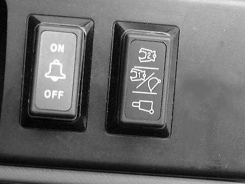
CD00E010 3. Use the upperstructure swing locking switch on the systems display and control panel and make sure the locking indicator lamp lights up on the display panel.
CD00E080 6. Stop the engine and remove the starter switch key.
CD00E060 4. Turn the engine throttle button to low idle position and let the engine run for approximately five minutes. 5. If necessary, activate the anti-theft device. See “Anti-theft protection”.
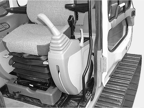
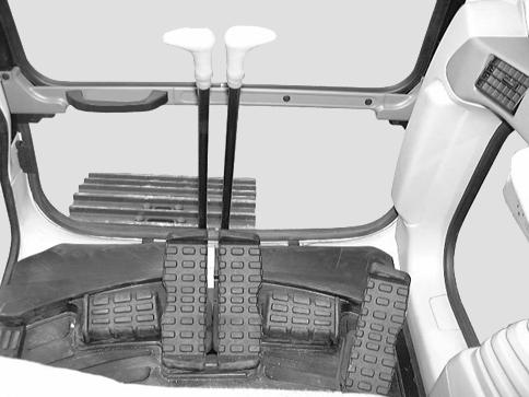
CD00E005 7. Raise the function cancellation lever (safety bar in inward position).
WARNING: Never jump down from the machine. When alighting from the operator’s compartment, or from the upperstructure, always face the machine and use the steps and access handles.
110
TRIM THIS EDGE LEFT PAGE
IMPORTANT: Check that the no part of the machine is encroaching on the highway. If this cannot be avoided, set up approved traffic signs.
CD00E002 8. Lock the operator’s compartment door and make sure that the hoods, lower panels and side doors are properly fastened.

TOWING THE MACHINE
Before attempting to tow the machine, consult your CASE Dealer. Wherever possible, carry out any repairs at the site.
WARNING: Towing is a delicate maneuver which is always carried out at the risk of the user. The manufacturer’s warranty does not apply to incidents or accidents which occur during towing. Where possible, carry out the repairs at the site.
WARNING: The machine must be towed very slowly, over a short distance and only if it is really unavoidable.
WARNING: The operator must be the only person on the machine when towing. Make sure that nobody else is on the machine or within its working range. TRIM THIS EDGE
111
TRIM THIS EDGE RIGHT PAGE
Template Name: OM_1_colTemplate Date: 1994_04_29
Template Date: 1994_04_29Template Name: OM_1_col

LOWERING THE ATTACHMENT IN THE EVENT MACHINE FAILURE
If the engine breaks down, use the following procedure to lower the attachment:
TRIM THIS EDGE
CD00E060 1. Turn the starter switch key to the “ON” position.
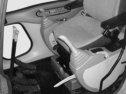
CD00E111 3. Place the control lever (s) in the position corresponding to the downward movement requiered.
CD00E006 2. Lower the function cancellation lever (safety bar in outward position).
112
TRIM THIS EDGE LEFT PAGE
HYDRAULIC BREAKER OR HIGH FLOW HYDRAULIC CIRCUITS (optional) (except CX210LR and CX240LR)
Your machine has two types of auxiliary hydraulic circuit. One circuit is for single flow equipment, such as hydraulic breakers. The second circuit is for single flow or double flow continuous flow equipment, or double flow equipment such as concrete crushers. Consult your CASE Dealer for instructions on how to select the correct pressure for the optional tool.
Hydraulic breaker configuration
A24690 1. Using a hexagonal wrench, place the supply valves in “O” (open) position. See “Optional tool supply valves” in the “Controls/Instruments/Accessories” Section. 2
CD00E072 3. Tilt the control (2) on the left-hand arm to the right for hydraulic breaker operation.
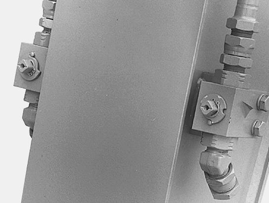
1
CD00E070 2. Remove the screw (1), place the flow selector valve in position (B) and then install the screw (1).

CD00E012 4. Use the control pedal to operate the hydraulic breaker.
113
TRIM THIS EDGE RIGHT PAGE TRIM THIS EDGE
Template Name: OM_1_colTemplate Date: 1994_04_29
Template Date: 1994_04_29Template Name: OM_1_col


TRIM THIS EDGE
CD00E082 5. When removing the hydraulic breaker, place the supply valves in “S” position (closed) and plug the orifices. 6. Tilt the control (2) to the central position.
Double flow concrete crusher configuration
A24690 1. Using a hexagonal wrench, place the supply valves in “O” (open) position. See “Optional tool supply valves” in the “Controls/Instruments/Accessories” Section.
1
CD00E071 2. Remove the screw (1), place the flow selector valve in position (C) and then install the screw (1).
114
TRIM THIS EDGE LEFT PAGE