35
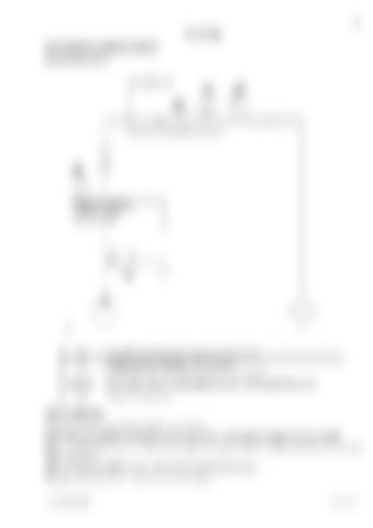
TESTING MEASURING HAMMER CIRCUIT MEASURING POINTS
FLOWMETER
HAMMER CONTROL VALVE OR MAIN VALVE BLOCK
p0
tank (with closed circuit from suction pipe of the pump).
p2
straight before the restriction of the flow meter (e.g. Webster flow meter includes pressure gauge for p2)
Q2 & T2 p3
at flow meter, which connects pressure and return line of the hammer circuit. straight after flow meter.
HOW TO MEASURE Procedure for measuring and adjusting the hammer circuit. Note: Check and calibrate all the gauges you are going to use . Faulty pressure gauges should be changed. Note: If the flow to the hammer is adjusted by changing the engine revolutions, always check the flow also at full engine revolutions. Note: It is absolutely forbidden to use hammer above specified oil flow range. Warning : Don’t exceed the carrier’s main relief valve setting.
Lep SMCB18S-1EN
Issued 03-09


