17 minute read
SAFETY INSTRUCTIONS


The 788 is an all hydraulic machine. It consists of a P type undercarriage (of which there are 5 versions: P, PL, P2A, P2AL and P2A+2A) fitted with the travel components and the turntable bearing to which the upperstructure frame is attached. The upperstructure frame supports the attachments at the front of the machine and contains the engine, the hydraulics and the operator’s compartment. When the operator works the controls, the engine driven variable flow pump delivers hydraulic fluid to the control valves. The control valves distribute the hydraulic fluid to the various cylinders and hydraulic motors. A cooling system and oil cooler maintain the fluid temperature at normal working temperature.
Key to main components
1 Cab 2 Instrument panel/Control panel 3 Fuel tank 4 Swing reduction gear motor 5 Hydraulic swivel 6 Undercarriage 7 Dozer blade 8 Front axle 9 Hydraulic travel motor 10 Gearbox 11 Axle reduction gears 12 Tyres 13 Rear axle 14 Stabilizers 15 Turntable bearing 16 Upperstructure 17 Operator’s compartment 18 Swing control valve 19 Attachment control valve 20 Valve bank partition 21 Brake circuit filter 22 Batteries 23 Hydraulic filters 24 Hydraulic pump 25 Hydraulic reservoir 26 Air filter 27 Counterweight 28 Engine hood 29 Radiator and oil cooler 30 Engine 31 Valve bank partition hood 32 Stabilizer beam 33 Selection block circuit filter
15
TRIM THIS EDGE RIGHT PAGE TRIM THIS EDGE
Template Name: OM_1_colTemplate Date: 1994_04_29
Template Date: 1994_04_29Template Name: OM_1_col
TRIM THIS EDGE
MACHINE COMPONENTS (788CompactSeries,P2ALVersion)
1 31 28 22 29 30 26 27
3
18
16
4
5 6
7
8 2 20
33 25
23 24
17 21 19
32
15 14
9 13
10
11
16 12
CS96C210
TRIM THIS EDGE LEFT PAGE
The 788 Compact is an all hydraulic machine. It consists of a P type undercarriage (of which there are 5 versions: P, PL, P2A, P2AL and P2A+2A) fitted with the travel components and the turntable bearing to which the upperstructure frame is attached. The upperstructure frame supports the attachments at the front of the machine and contains the engine, the hydraulics and the operator’s compartment. When the operator works the controls, the engine driven variable flow pump delivers hydraulic fluid to the control valves. The control valves distribute the hydraulic fluid to the various cylinders and hydraulic motors. A cooling system and oil cooler maintain the fluid temperature at normal working temperature.
Key to main components
1 Cab 2 Instrument panel/Control panel 3 Fuel tank 4 Swing reduction gear motor 5 Hydraulic swivel 6 Undercarriage 7 Dozer blade 8 Front axle 9 Hydraulic travel motor 10 Gearbox 11 Axle reduction gears 12 Tyres 13 Rear axle 14 Stabilizers 15 Turntable bearing 16 Upperstructure 17 Operator’s compartment 18 Swing control valve 19 Attachment control valve 20 Valve bank partition 21 Brake circuit filter 22 Batteries 23 Hydraulic filters 24 Hydraulic pump 25 Hydraulic reservoir 26 Air filter 27 Counterweight 28 Engine hood 29 Radiator and oil cooler 30 Engine 31 Valve bank partition hood 32 Stabilizer beam 33 Selection block circuit filter
17
TRIM THIS EDGE RIGHT PAGE TRIM THIS EDGE
Template Name: OM_1_colTemplate Date: 1994_04_29
Template Date: 1994_04_29Template Name: OM_1_col
TRIM THIS EDGE
SAFETY INSTRUCTIONS
Your safety and that of people around you depends on you. It is important that you understand this manual for the correct operation, inspection, lubrication and maintenance of this machine.
Read this manual carefully and make sure that: -You understand the symbols on the controls and the safety signs used in this manual and on the machine.
-You understand the speed, stability, braking and steering characteristics of the machine. If you are in any doubt, consult your CASE Dealer. The safety messages in this manual concern situations which may arise during normal machine operation and servicing. These safety messages also give possible ways of dealing with these situations. Other safety messages are used throughout the manual to indicate specific dangers. Whatever type of work is being done (earthmoving, handling, drilling, etc.), the safety measures for private or public work sites must conform to current regulations in the country concerned and in the type of operation concerned (mining, quarrying, tunnelling). The safety instructions given in this manual are a summary of the basic rules to be observed at all times and do not exempt you from insurance requirements or from abiding by the highway code. Always keep this manual in the storage compartment provided for it. Make sure it is always complete and in good condition. If you wish to obtain additional manuals, consult your CASE Dealer.
18
TRIM THIS EDGE LEFT PAGE
BEFORE USING THE MACHINE
• Do not attempt to operate this machine unless you have first read and understood the safety messages and warnings which appear in this manual. • Operating the machine requires your full attention. Care on the part of the operator can help avoid accidents. Get to know the machine’s capabilities and limitations and the working space required. There are areas of poor visibility in the working range of the machine. Have someone guide you for all work where visibility is poor. • Grease, oil, mud or ice (in winter) on the steps and access handles can cause accidents. Make sure they are kept clean at all times. • Before starting each day, walk around the machine and check for oil or hydraulic fluid leaks. Tighten and replace as necessary. • Check the hardware used to mount the main components: counterweight, turntable bearing, front and rear axles, wheels and operator’s compartment.
In the event of problems, contact your
CASE Dealer.
• Remove any obstructions which hinder visibility. Clean the windshield, the windows, the forward and rear view mirrors.
• Make sure you are perfectly familiar with hand signals in use on the job site so that you can obtain help with tight maneuvers or when visibility is poor. • Make sure that the steering column is tilted towards the driver and securely locked. • Before driving or operating the machine at night, make sure that the lights and signalling equipment are in proper working order. • Before travelling, make sure all doors, access panels and hoods are properly locked or fastened.
• Check that no tools or other items have been left on the machine (the undercarriage or the upperstructure) or in the operator’s compartment. • The operator must be the only person on the machine. Make sure there is no-one else on or around the machine.
• The upperstructure must be aligned with the undercarriage and preferably in road travel position when getting in or out of the operator’s compartment. • Always face the machine and use the steps and access handles when getting in or out of the operator’s compartment.
• Be sure you know the position and function of each control. Incorrect operation of controls can cause serious injury. • Check all controls and safety devices in a safe, open area before starting work.
• Keep away from dangerous areas such as ditches, overhangs, unstable ground, etc... Walk around the job site and identify any dangers before starting work.
19
TRIM THIS EDGE RIGHT PAGE TRIM THIS EDGE
Template Name: OM_1_colTemplate Date: 1994_04_29
Template Date: 1994_04_29Template Name: OM_1_col
TRIM THIS EDGE • Inspect and identify all possible dangers before operating the machine in a new area. Holes, obstacles, piles of rubble and other potential sources of danger on the job site can cause serious injury. • Be prepared in emergencies. Always carry a first aid kit and fire extinguisher within easy reach on the machine.
Make sure that the fire extinguisher is regularly serviced according to the manufacturer’s instructions.
• Make sure you understand the symbols used on the machine safety decals. Make sure that the decals are clean and legible at all times. • Familiarize yourself with the machine’s emergency exits (emergency exit via the windshield) in the event of the cab door being jammed or the machine turning over. • Before travelling on the road, make sure that the load on each axle, depending on the machine configuration, conforms to the road traffic regulations of the country concerned. • Before travelling on the road, make sure that the cab door is closed and properly fastened. • Before travelling on the road, lock the attachments and install the safety systems required by regulations. Raise the stabilizers (if fitted) completely, raise the dozer blade (if fitted) and immobilize them by means of the safety systems provided. • Check the condition and pressure of the tyres regularly. • If the machine is equipped with a
Quick Coupler (optional), it is important to make sure that the switch is in the locked position when the operating the machine.
• If the machine is equipped with a
Quick Coupler (optional), it is important to make sure that the safety retaining pin and split pin are correctly installed in the Quick Coupler.
20
TRIM THIS EDGE LEFT PAGE
MACHINE OPERATION
• When working on a public highway, use standard traffic signs, taking into consideration the working range of the upperstructure and its attachments.
Local or national regulations stipulate the number, type and location of reflector strips. • Avoid running the engine in an enclosed area. If there is no alternative, make sure there is proper ventilation at all times.
• Do not allow anyone else on the machine. The passenger could fall or cause an accident.
• Operate the working or travel controls only when seated in the operator’s seat.
• When working near overhead high voltage electric lines, you must keep a safe working distance from the lines.
The minimum distances to be respected are as follows:
Under 57 000 volts: 3 meters.
Over 57 000 volts: 5 meters.
• Locate the position of any underground pipes or conduits before starting work. Electrical cables, gas pipes, water pipes or other underground installations can cause serious bodily injury. • Always make allowance for working conditions (sloping or rough ground), the road surface and weather conditions when driving the machine. • Do not allow anyone within the machine’s working area. An accident can occur if the operator operates the swing control or an attachment control accidentally. Stop all operations until everyone has moved away. • If the machine is equipped with a
Quick Coupler (optional), never tilt the switch to the unlocked position while the machine is being operated. • Make sure that there is nobody within the operating range of the stabilizers (if fitted) or the dozer blade (if fitted) before operating them. • Operate all controls gradually to ensure smooth machine operation. • When travelling with a load or driving the machine onto a trailer, always use the travel control lever to maintain full control of the machine’s travel speed. • The front axle must be unlocked for all travel operations. • The front axle must be unlocked when loading or unloading the machine on or off a transport trailer.
21
TRIM THIS EDGE RIGHT PAGE TRIM THIS EDGE
Template Name: OM_1_colTemplate Date: 1994_04_29
Template Date: 1994_04_29Template Name: OM_1_col
TRIM THIS EDGE • Load handling operations must always be carried out with strict adherence to the instructions given in this manual and to current legislation. • Load handling operations must be carried out with the front axle locked and with the machine in work position. • If the machine is equipped with a
Quick Coupler (optional), never use the front or rear anchorage points of the Quick Coupler for handling loads. • In certain configurations, a swinging attachment may cause interference between the attachment tool and the operator’s compartment. Always keep a safe working distance between the attachment tool and the operator’s compartment (in case of tool swinging or accidental movements). • Never use the attachment for sweeping the ground to level out rubble or push objects (transverse stress on the attachment). • Stop the engine and remove the starter switch key when the machine is not in use, even for short periods of time.
• Never leave the operator’s compartment while the engine is running. • The left-hand control arm must be raised when entering or leaving the operator’s compartment. Never forget this basic requirement. • The upperstructure must be aligned with the undercarriage and preferably in road travel position when getting in or out of the operator’s compartment. • Dust, smoke or fog can reduce visibility and cause an accident. Reduce speed or come to a complete stop until visibility has improved. • Never jump down from the machine.
Always face the machine and use the steps and access handles when dismounting from the cab or the upperstructure.
• If a malfunction occurs or if the machine is damaged, move the machine to a safe place, lower the attachment to the ground with the dipper cylinder rod and the bucket cylinder rod completely retracted or completely extended. Stop the engine and remove the starter switch key.
Locate the problem, report it, and if necessary warn others not to attempt to operate the machine. • All road travel must be undertaken in forward drive, with the operator’s compartment over the front wheels. • Use of the electric travel control (if fitted) is strictly forbidden during road travel.
• Road travel which requires the use of dipped or main-beam headlights (travel at night, in a tunnel or in poor weather conditions, etc.) must only be undertaken with attachments in road travel position and with tools (bucket or clamshell) less than 1.05 m, in order to conform to lighting regulatory requirements.
22
TRIM THIS EDGE LEFT PAGE
• When parking on a slope, use the wheel blocks to immobilize the machine. • If the machine is equipped with a
Quick Coupler (optional), never put your hands in the Quick Coupler and never attempt to make any adjustments or repairs while the engine is running.
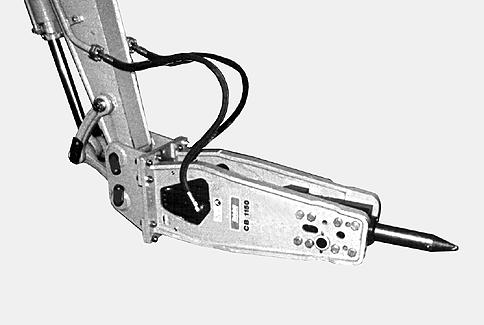
USING THE HYDRAULIC BREAKER (optional)
• Protect yourself and the vicinity from flying chips of rock. • Wear ear protection when working with the machine door or windows open. • Never immerse the hydraulic breaker in water as this could cause damage. • Do not operate the hydraulic breaker with the attachment cylinders up to the end of their stroke (extended or retracted). • Do not operate the hydraulic breaker if the tool is in contact with some part of the machine.
• Place the tool against the object at a 90 degree angle. Avoid small irregularities on the object which will break easily and cause either idle strokes or an incorrect working angle. • When demolishing vertical structures (e.g brick walls), place the tool against the wall at a 90 degree angle. • Use a safety screen to protect yourself from flying debris. Keep the cab windows closed during operation. • Listen to the noise the hydraulic breaker makes while you are using it.
If the pitch of the noise rises and, at the same time, the force of impact diminishes, this means that the tool is not properly aligned with the material and/or that there is not enough downward force on the tool. Realign the tool and press it firmly against the material. • Do not strike in one spot for more than 15 seconds at a time. If the object does not break, or if the tool does not penetrate, stop the breaker and change the position of the tool. • For the hydraulic breaker to be most effective when breaking boulders work progressively in small steps from the outer edge towards the middle. • When breaking hard or frozen ground, use the benching method. Start by clearing a small area working from the edge. Then continue by breaking material towards the open area.
23
TRIM THIS EDGE RIGHT PAGE TRIM THIS EDGE
Template Name: OM_1_colTemplate Date: 1994_04_29
Template Date: 1994_04_29Template Name: OM_1_col
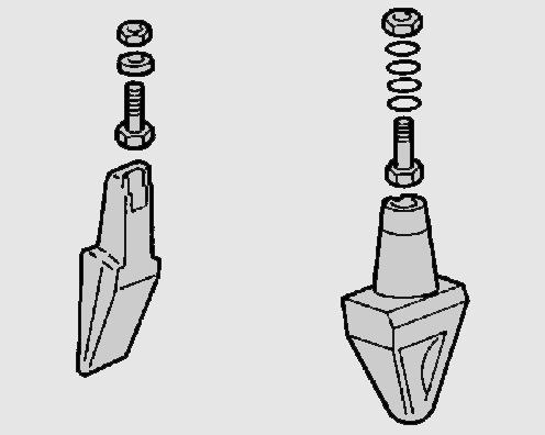
TRIM THIS EDGE • Do not operate the hydraulic breaker in the air, with nothing to hit. Frequent idle strokes have a deteriorating effect on the hydraulic breaker. • When breaking concrete, hard or frozen ground, never strike and pry with the tool at the same time. The tool may snap off. Bending may be caused by stones inside hard or frozen ground.
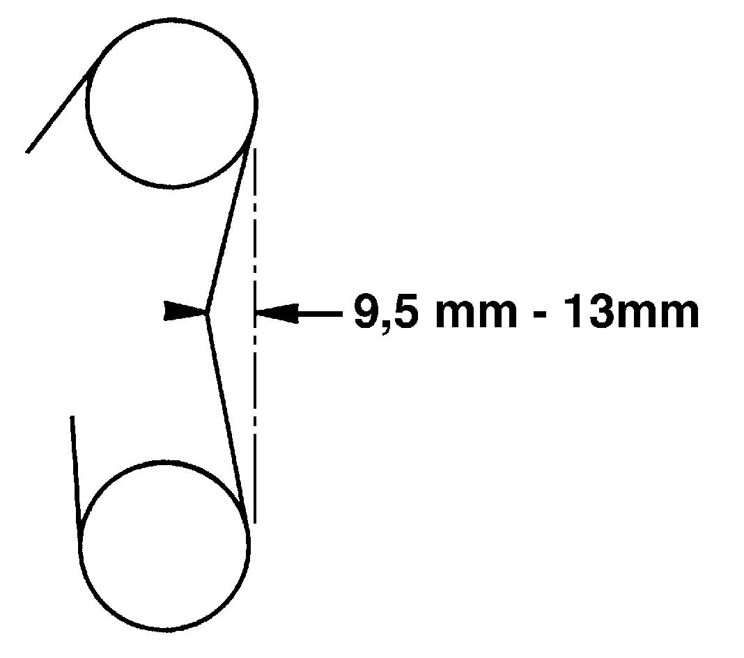
Be careful and stop striking if you encounter sudden resistance under the tool. • Keep the tool at a 90 degree angle at all times. If the object moves or if its surface breaks, correct the angle immediately. Keep the hydraulic hydraulic force and tool aligned. • The tool shank should be kept well greased during operation. Regular visual checks should be made during operation.
PARKING THE MACHINE
• When parking the machine, proceed as follows:
1.Park the machine on flat, level ground, away from soft ground, excavations or poorly shored cavities. 2.Align the upperstructure with the undercarriage, retract the attachment and anchor the bucket or clamshell in the ground. 3.Raise the stabilizers (if fitted) completely and immobilize them using the lock pins and split pins. 4.Raise the dozer blade (if fitted) and immobilize it using the lock pin and split pin. 5.Place the travel control lever in the neutral position. 6.Engage the upperstructure swing lock pin. 7.Use the parking/work brake control switch to immobilize the machine. 8.Stop the engine and remove the starter switch key. 9.The left-hand control arm must be raised before leaving the operator’s compartment. 10.Lock the cab door.
11.Switch off the electrical system using the battery master switch key. 12.Make sure that the doors, hoods and access panels are securely locked or fastened.
13.Check that no part of the machine is blocking the roadway. If this cannot be avoided, set up the necessary traffic signs, as required by regulations.
24
TRIM THIS EDGE LEFT PAGE
MAINTENANCE AND ADJUSTMENT
• Do not attempt to service this machine unless you have first read and understood the safety messages and warnings which appear in this manual. • When servicing this machine, always wear suitable clothing. Avoid loose-fitting clothing. • When servicing the machine, put a
“Do not operate” tag on the instrument panel. • Always wear eye protection when using a tool that might project metal particles. Use a hammer with a soft face, such as copper, for installing pins. • Poorly performed maintenance or adjustments can cause serious injury.
If you do not understand a maintenance or adjustment procedure, consult your CASE Dealer. • Respect the maintenance intervals and check the hardware used to mount the main components: counterweight, turntable bearing, front and rear axles, wheels and operator’s compartment. In the event of problems, contact your CASE Dealer. • Leaving the attachment in the raised position or machine movements without an operator can cause serious injury. Before performing any service work, the following steps must be carried out:
1.Park the machine on flat, level ground. 2.Lower the attachment until it is resting on the ground. 3.Stop the engine and remove the starter switch key. 4.Block the wheels to prevent any machine movement.
• Unauthorized modifications to the machine can cause serious injury. Do not make any modifications to this machine without prior authorization from your CASE Dealer. Any modifications made must conform to the machine’s technical specifications and adhere to current safety regulations. • Certain components of the machine must comply with approved standards.
When replacing such components, it is necessary to ensure that they conform to regulations. As a safety measure, use genuine CASE parts. TRIM THIS EDGE
25
TRIM THIS EDGE RIGHT PAGE
Template Name: OM_1_colTemplate Date: 1994_04_29
Template Date: 1994_04_29Template Name: OM_1_col
TRIM THIS EDGE • If pressurized hydraulic fluid penetrates the skin, it can cause serious injury. Take the necessary safety precautions (protective clothing and face and hand protection) to prevent such risks. In addition, before using these products, read the manufacturer’s instructions for use. If hydraulic fluid penetrates the skin, call a doctor immediately. • When welding on the undercarriage or the upperstructure frame, as authorized by the manufacturer and in accordance with his specifications, disconnect the batteries, disconnect the
B+ and D+ alternator wires, remove the electronic control box and connect the welding apparatus earth cable to the component on which the welding operation is to be performed. Never connect the welding apparatus earth cable to the undercarriage when welding on the upperstructure (or viceversa). Never connect the welding apparatus earth cable to a component of the hydraulic system. • Always wear face protection when using compressed air. • A burst tyre can cause serious bodily injury. Check the condition of tyres regularly and always maintain the recommended inflation pressure. • When checking pressure or inflating a tyre, never stand in front of the tyre.
Always face the tread. Always use an inflation cage when the wheel is removed from the machine. Do not allow anyone in the area. • Never weld close to a tyre. The tyre must be removed for all welding operations.
26
TRIM THIS EDGE LEFT PAGE