2 minute read
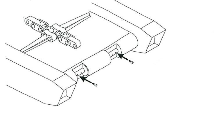
Tail roller.......................................................................5


BI016907-02-EN
Advertisement
– install desiccant breathers on all bulk tanks
– use sealed plastic containers for adding oil to small sumps
– locate bulk tanks near equipment and pump directly to reservoirs
– utilize filter carts to maintain oil cleanliness standards
– properly train personnel on the importance of clean oil and best practices for storage and handling
– monitor your program closely and look for continuous improvement
2. Eliminate contamination source through “clean” maintenance practices.
This is best achieved by understanding the primary sources of contamination during maintenance and troubleshooting which are given below:
– always clean the area around the component that is to be removed and inspected
– store components in a plastic bag after inspection and prior to replacement on machine
– cap off all open hoses/fittings
– never touch a filter with bare hands when installing it back onto the machine
– pay close attention to the filler/breather cap and replace it when damaged or in the recommended time frame
Contact your representative for more information on implementing an effective program to ensure that your oil and maintenance practices are not contributing to your equipment failure.
Specific hydraulic circuit troubleshooting
Multi-function failure
If more than one function fails to operate on the machine, check the output of the pumps. Since this is an “open center” circuit, the normal pressure (with all directional control valves in the center position) should be less than 100 psi. This pressure reading illustrates the necessary pressure to circulate the oil through the system. If the pressure reading under these conditions is significantly greater than 100 psi, it is likely that one of the control valves is trying to direct oil to one (or more) of the circuits on the machine.
BI016907-02-EN
The next step in troubleshooting a multi-function failure is to check the pilot pressure on the main control valve manifold. This pressure should be between 400 - 500 psi. If the pilot pressure is significantly below 350 psi, start with the General Troubleshooting Flow Chart IV - Incorrect Pressure. Another step to resolve multi-function failure is to have an electrician check for power to the solenoid circuits.
Individual hydraulic circuit failures
Perform the following checks on the individual circuits in conjunction with the general troubleshooting:
Oil tank fill
Check the venturi ejector for blockage.
Check for low oil in the new oil supply.
Cutter head raise
Check the directional control valve for proper operation.
Check to see that hosing has not been crossed, especially if the problem occurs after maintenance or repair work.
Check that the "in-line" counterbalance holding valve is piloted and shifting to direct retract port cylinder oil flow back to tank.
Check to see that there is no mechanical bind.
Check cylinders for bypassing.
Check for pilot pressure on the cutter head cylinder’s holding valves. Also check that the valves are shifting to send (extend port) oil back to the tank.
Cutter head lower
Check the direction control valve for proper operation.
Check to see that hosing has not been crossed, especially if the problem occurs after maintenance or repair work. Check to see that there is no mechanical bind or hydraulic block. Check flow control valve cartridge.
Check cylinders for bypassing.
Check for pilot pressure on the cutter head cylinder's holding valves. Also check that the valves are shifting to send (extend port) oil back to the tank. Note: Cylinder removal will be required to safely achieve this.