1 minute read
Front idler take-up cylinder...........................................5

Hydraulic pump installation
Advertisement
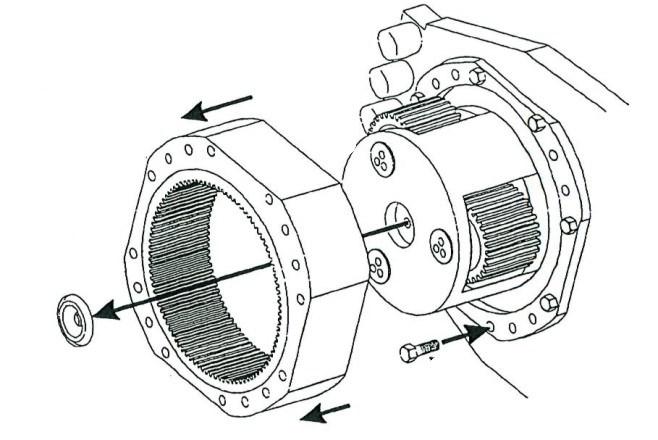
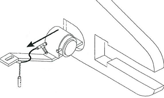
1. Slide the pump assembly into the pump motor (Fig. 201).
2. Insert and tighten, all hex head capscrews and lockwashers to secure the pump assembly to the motor.
Fig. 201: Hydraulic pump installation
Motor
Hex head capscrew Pump
Lockwasher
3. Insert the hydraulic hose fittings into the pump assembly and tighten.
4. Attach and tighten the exit pilot and valve hoses to the pump fittings.
5. Attach the inlet hose to the pump.
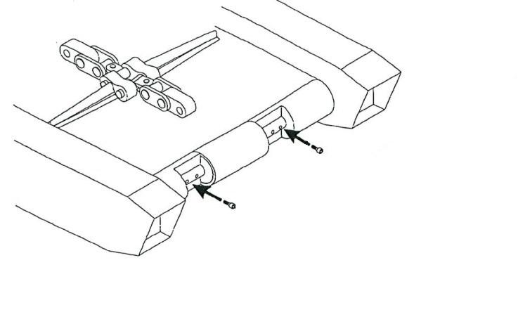
6. Replace the rub rail between the two adjacent rub rails and secure it with the two rub rail pins.
7. Check the hydraulic fluid level.
8. Jog pump motor on and off a few times to prime the pump before starting.
BI016907-02-EN
Hydraulic pump motor removal
1. Lower the conveyor tail section it is level with the floor.
2. Lower the gathering head and cutter head until they touch the floor.
3. Disconnect the trailing cable to de-energize the miner. Follow all Federal and mine regulations for lockout/tagout.
WARNING! Follow all federal and mine lockout/tagout regulations. Failure to do so could result in machine damage or serious injury or death to personnel.
4. Remove the hydraulic pump (see Hydraulic pump removal procedure in this chapter).
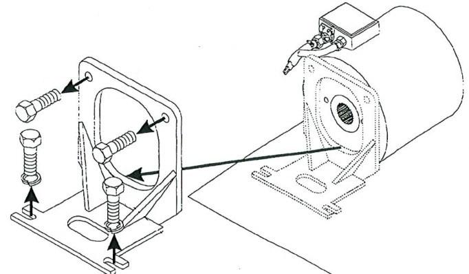
5. Remove the two hex head capscrews that secures the motor to the pump stand (Fig. 202).
6. Remove the two hex head capscrews and lockwashers that secure the pump stand to the tractor frame and remove the pump stand.
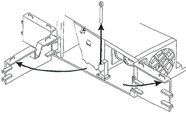
Fig. 202: Hydraulic pump stand removal
Hex head capscrew (2)
Pump stand
Hex head capscrew (2) Motor