2 minute read
Tram track front idler....................................................5

BI016907-02-EN
Advertisement
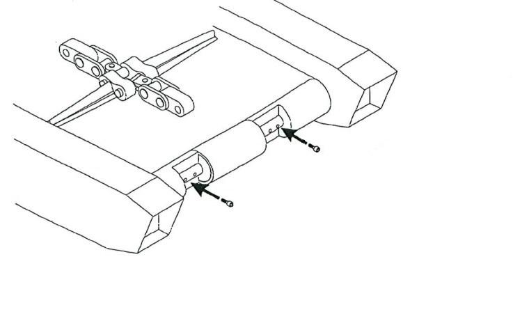
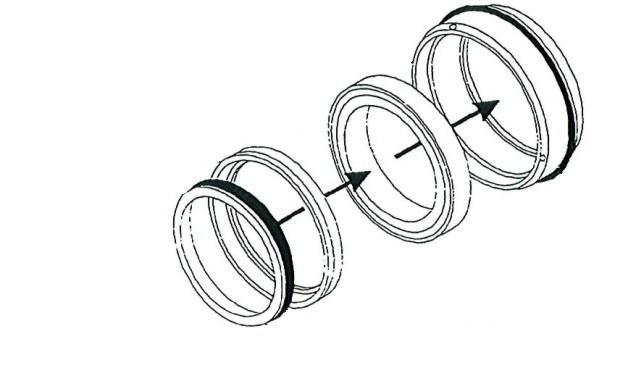
7. Pull the flip pin (Fig. 199) from the half link to release the takeup cylinder bracket from the tractor frame.
8. Lower the end of the bracket until it clears the half link and pull the bracket straight out to remove it from the tractor frame. If necessary, collapse the take-up cylinder.
Fig. 199: Front idler take-up cylinder removal
Bracket assembly Idler take-up cylinder assembly
Flip pin

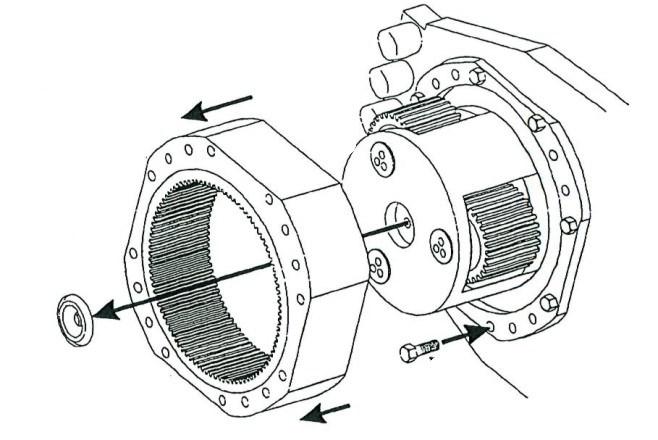
front idler cylinder installation
Flip pin Tractor frame
To install the front idler take-up cylinder:
1. Replace the take-up cylinder bracket assembly into the tractor frame and secure it by inserting the flip pin through the half link.
2. Replace the fill plate and secure with capscrews.
3. Close the front rub rail cover and secure to the tractor frame with a hex head capscrew and lock washer to secure the front rub rail to the tractor frame.
Hydraulic pump removal
1. Lower the conveyor tail section until it is level with the floor.
2. Lower the gathering head and cutterhead assemblies until they rest on the floor.
3. Disconnect the trailing cable to de-energize the miner. Follow all Federal and mine regulations for lockout/tagout.
WARNING! Follow all federal and mine lockout/tagout regulations. Failure to do so could result in machine damage or serious injury or death to personnel.
There are two alternative locations and instructions for the removal of the hydraulic pump: in front of the demister box or behind the operator’s case.
When located in front of the demister box:
4. Locate the rub rail directly behind the tram case on the scrubber exhaust side of the miner (Fig. 200). Remove the two rub rail pins that secure the rub rail to the two rub rail sections adjacent to it and remove the rub rail.
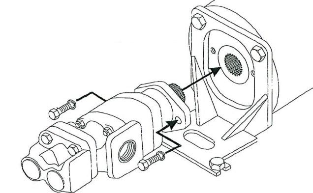
Fig. 200: Pump located behind demister
Hydraulic pump
Scrubber exhaust

Rub rail
5. Locate the hydraulic pump and motor assembly (Fig. 200).
6. Using the adjustable wrench, disconnect the inlet hose from the pump. Plug the hose end to keep it clean.
7. Using the adjustable wrench, disconnect the pilot and valve hoses from the pump fittings. Plug the hose ends to keep them clean.
BI016907-02-EN
8. Remove the hose fittings from the pump and store in a safe place.
9. Remove all hex head capscrews and lockwashers that secure the pump assembly to the motor assembly and save for reinstallation.
10. Carefully remove the pump assembly by sliding it out of the pump motor.
When located behind the operator’s case:
4. Locate the rub rail directly behind the tram case on the operator’s side of the miner. Remove the two rub rail pins that secure the rub rail to the two rub rail sections adjacent to it and remove the rub rail.
5. Locate the hydraulic pump and motor assembly.
6. Using the adjustable wrench, disconnect the inlet hose from the pump. Plug the hose end to keep it clean.
7. Using the adjustable wrench, disconnect the pilot and valve hoses from the pump fittings. Plug the hose ends to keep them clean.