6 minute read
Swivel pin assembly.....................................................5

BI016907-02-EN
Advertisement
Chain replacement
1. Lower the cutter head and gathering head assemblies until they touch the ground.
2. Position the conveyor tail section directly behind the miner and raise it. Insert the blocking under the tail section and lower the tail section onto the blocking.
WARNING! You could be seriously injured or killed by falling loads. Observe the safe working load limits of all blocking devices.
3. Disconnect the trailing cable to de-energize the miner. Follow all Federal and mine regulations for lockout/tagout.
WARNING! Follow all federal and mine lockout/tagout regulations. Failure to do so could result in machine damage or serious injury or death to personnel.
4. Loosen the tension of the conveyor chain as much as possible (see Conveyor chain adjustment procedure in this chapter).
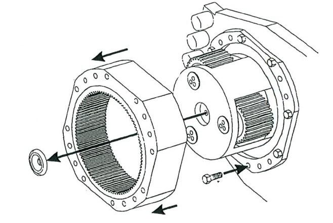
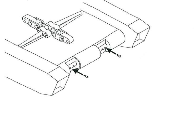
5. Remove the two retaining rings from a connecting link located near the rear of the conveyor bed.
6. Remove the connecting link. The chain is now separated.
7. Connect the come-along to the end of the chain on the conveyor bed.
8. Connect the new chain to the end of the lower chain and allow the new chain to extend behind the miner on the floor.
9. Use the come along to pull the old chain out of the miner. The new chain will follow the old through the conveyor return channel around the gathering head foot shaft and out onto the conveyor tail section.
10. When the entire length of old chain has been pulled through the miner and the replacement chain is in position, disconnect the old chain from the new and remove the come along.
11. Connect both ends of the new chain by replacing the connecting link, pins and retaining rings.
12. Tighten the conveyor chain (see Conveyor chain adjustment procedure in this chapter).
BI016907-02-EN
Troubleshooting procedures
The following section lists possible problems encountered when servicing the Continuous Miner and can aid in locating and correcting these problems.
This section covers basic components, with each listed in a troublecause-remedy format.
WARNING! Some procedures must be carried out with the cover of the electrical controller removed and some procedures require the controller to be energized during the tests. It is extremely important that you take all necessary precautions to prevent accidental electrical shock while working within the controller. An MSHA-certified electrician must supervise and inspect all work performed.
For maintenance procedures and tests that DO NOT require the controller to be energized, these precautions include:
■ Before removing the controller cover, remove power from the system by disconnecting the trailing cable. Follow all mine, local, State, and Federal lockout/tagout procedures.
■ Use insulated gloves and tools where possible.
■ All connections must be tight and care must be taken to pre vent bolts, nuts, washers and other small metal fasteners from being dropped or lost inside the controller. These lost fasteners could cause electrical shorts inside the controller.
For procedures that DO require that the controller be energized while the cover is off:
■ At no time should you reach inside the controller while it is energized. If it becomes necessary to make adjustments or to replace parts inside the controller, the machine circuit breaker must be turned to the “OFF” position. Once the circuit breaker is in the “OFF” position, adjustments or parts replacements can be made.
■ Use insulated gloves and tools where possible.
■ All connections must be tight and care must be taken to pre vent bolts, nuts, washers and other small metal fasteners from being dropped or lost inside the controller. These lost fasteners could cause electrical shorts inside the controller.
BI016907-02-EN
WARNING! Never disconnect a hydraulic hose if the circuit is pressurized or there is a load on the circuit. If a hose is disconnected while the cylinder is supporting a load, the load will fall.
Typical hydraulic problems
The most common causes for improper function are:
■ contaminated oil or poor oil quality
■ low or insufficient oil in the system
■ using the wrong type of oil or wrong viscosity grade
■ air in the hydraulic system
■ internal or external leakage of the hydraulic system
■ improper mechanical adjustments, such as reliefs
■ mechanical or structural damage leading to component failure
■ components by-passing (internal leaking or inability to hold pressure) which leads to erosion of bushings, valve spools, and other costly, critical components
The greatest aid to troubleshooting a hydraulic system is the confidence that comes with knowing the intended operation of the system, along with a fundamental understanding of basic hydraulic principles. Every component in the system has an intended purpose. The construction and operating characteristics of each of these components should be clearly understood before attempting to troubleshoot the machine. For example, understanding that a solenoid controlled directional valve can be manually actuated will save considerable time in isolating a defective solenoid. Please familiarize yourself with the operational descriptions of the hydraulic circuits given in the Hydraulics section of this chapter.
It is also important to know the capabilities of the system. Each component in the system has a maximum rated speed, flow, torque, or pressure. If the system is loaded beyond the specifications, the possibility of failure is greatly increased. The correct operating pressures of a system must be known and must always be checked and set with a pressure gauge. Refer to the hydraulic schematic in the parts manual supplied with your machine for the correct operating parameters. When in doubt, always assume that the correct pressure is the lowest pressure that will allow adequate performance of the system function (s) while remaining below the maximum rating of the machine’s components.
BI016907-02-EN
The ability to recognize trouble indicators in a specific system is usually acquired with experience. the gaining of this experience can be greatly enhanced by developing a logical sequence for determining the cause of a hydraulic problem and implementing the proper remedy.
Refer to the general troubleshooting charts in this section that illustrate the logical sequence for shutdown, troubleshooting, and restarting the machine. The charts cover:
■ general safety procedure for shutting down the machine
■ troubleshooting excessive noise
■ troubleshooting excessive heat
■ troubleshooting incorrect flow
■ troubleshooting incorrect pressure
■ troubleshooting faulty movement/operation
■ general restart checklist and procedure
This general information is intended to enhance the understanding of basic hydraulic principles which will lead to the development of a logical troubleshooting procedure. Specific troubleshooting checklists for each hydraulic circuit are given directly after the very important section entitled “Contaminants in hydraulic systems”.
Contaminants in hydraulic systems
SYSTEM CONTAMINATION is the primary cause of hydraulic component failure! Cleanliness must be a high priority when servicing the hydraulic system. Even very small particles can damage system components by scoring valves, clogging orifices, and wearing seals prematurely. It is not the intent of this operation manual to outline a contamination control program but some of the most effective steps that have been identified in successful programs are given below:
1. Ensure that bulk oils are at acceptable cleanliness levels.
Areas where customers have made improvements in the past include:
– implement ISO Cleanliness Code standards for bulk hydraulic oils
– evaluate bulk oil shipments for cleanliness by conducting particle counts and maintain records
– minimize drum usage by utilizing tote tanks and five gallon pails
– utilize plastic versus steel storage tanks, if possible