12 minute read
11.0.3 Explanation of probable causes and how to remedy them


Order number Date Valid from serial number T-code
232020-040 2006-06-19 3 300 000- 805, 813, 830
1. Checking the battery and charger
1.1 Checking the battery
An old battery may be run down or the battery charger may be broken. Systems with low power consumption discharge a battery completely to a point where it only yields 8 or 9 V. If no power is being drawn from the battery, 12 V is always shown. This is because the voltage only falls when power is being drawn from the battery.
Therefore, when checking the battery’s voltage, the indicator must first receive power for several seconds or even minutes. If the voltage then drops slowly, you can conclude that the battery is run down.
The simplest way to test the battery is to replace the battery module.
Always check the battery charger. The charger must have an output voltage between 12.5 and 14 V. 1.2 Changing the battery
Batteries run down over time. When the battery gets old or has been used a lot, it is best to replace it in order to avoid problems.
2. Control mechanism
2.1 Check whether the scale’s mechanics are jammed mechanically
Weigh yourself by standing on the four corners of the forks. Your weight must be identical on all four corners. The indication may vary by up to 1 kg. If so, then all load sensors are working normally and the mechanics are working well with light weights.
After this test the scale should be loaded with a normal or heavy load. Use the tare button and reset the display. Leave the weight on the scale and then stand on or beside the load. Each corner must show the same indication with a deviation of plus or minus 1 to 2 kg.
If the readings are not identical or the deviation is greater than 1 or 2 kg or if it is unstable, continue to section 2.2.
T-code Valid from serial number Date Order number
805, 813, 830 3 300 000- 2006-06-19 232020-040
2.2 Trying to determine why weighing and non-weighing components are in contact with each other
It may be necessary to dismantle the pallet truck in order to locate the fault. There are usually scratches in the paint where mechanical parts are jamming. If in doubt, you can position a sheet of paper between weighing and non-weighing components. When the scale is then loaded with a maximum load and the load is moved laterally, traces on the paper can indicate where friction is occurring in the system.
Determine what is mechanically feasible to eliminate the friction, e.g. alignment of the load sensors and the upper fork connectors, reduction of the lifting mechanism’s movement margin by adjusting the pressure rods or load wheel holder. It may be necessary to adjust the load wheels’ pressure rods to prevent them touching the load sensors. Remember that friction cannot always be detected on an empty pallet truck. So check whether the lifting rods can touch the load sensors when you press them against the sensors. Clean the forks internally. 2.3 Have the load sensors been fitted correctly?
The load sensors have been secured with bolts. Check that the load sensors are fitted correctly. 2.4 Have the fork connectors been fitted correctly? (Always check this point!)
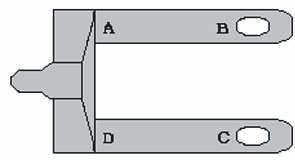
Check the underside of the pallet truck to see if the fork connectors have been fitted correctly and that they are not catching on the frame (the forks’ frame) at the sides. One common cause is friction in the load wheel shaft’s welded joint. Sometimes bits of wood or pebbles can cause friction between weighing and non-weighing components.
3. Checking the load sensors
3.1 If the scale’s indication is incorrect, you must check whether all load sensors are showing the same weight indication
Use your own weight to check this. Weigh yourself by standing on the four corners of the forks. Your weight must be identical on all four corners. There may be a variation in graduation. As the load sensors age or if one of them is replaced, the difference may sometimes be considerable. Continue to section 3.2 if the difference is substantial. 3.2 Checking whether the problem is due to the load sensors or the mechanism
Remove the fork connector (or the upper fork section). Insert bolts into the mounting holes on all the load sensors. Place a test weight of approximately 1 % of their capacity on each load sensor (on the bolts) and check whether each load sensor shows the same value.
The greatest difference must be no more than a ½ graduation. Continue to section 5 if the deviation is greater.
Order number Date Valid from serial number T-code
232020-040 2006-06-19 3 300 000- 805, 813, 830
3.3 If the indicator shows an error message or the reading is unstable
First try recalibrating the system.
Switch off the indicator and use an ohmmeter/voltmeter to measure whether the resistance in all wires between the load sensors and the pallet truck chassis is infinite. No resistance is permitted between the black, white and green wires between the load sensors and chassis.
The resistance between the disconnected excitation wires from the load sensors, i.e. the black and red wire, must be: +/- 350 ohm when one load sensor is checked +/- 87 ohm if all 4 load sensors are checked and they are connected in parallel.
These values must also be remeasured between the load sensors’ signalling circuits, i.e. the white and green wire.
When the indicator is receiving power, the following values must be displayed when the load sensors’ excitation wires (black and red) are remeasured: -Standard system without printer: 3.3 V. -System with commercial weighing status with/without printer: 2.5 V AC. As a result of a block voltage and depending on the voltmeter, a voltage of 2.2 or 2.5 volts may be measured. If not, the problem is with the indicator.
When the indicator is receiving power and the forks are empty, the following values must be measured between the load sensors’ signalling circuits (green and white): -Standard system without printer: 0.000 to 0.002 V. (V AC, with printer and/or trucks with commercial weighing status)
If the signal level is higher or negative, the load sensors are the cause. If the signal is only a little higher, the load sensors can still be used, but it is likely that this is only a short-term solution.
If the cause is found, the final test should be repeated with just one load sensor connected at a time to determine which load sensor(s) is causing the problem.
IMPORTANT:
An unstable reading can be measured using an ohmmeter/voltmeter if the deviation is large or if the ohmmeter/voltmeter provides a high level of accuracy.
3.4 Checking each load sensor, one at a time
In order to determine if only one load sensor is causing the problem, each load sensor must be connected separately to the indicator (and the indicator used as a voltmeter), and the measured values from the load sensors must be subsequently compared.
The different values must be almost identical. The value depends on the calibration setting. If a value is unstable or differs considerably from the other values, the load sensor in question must be replaced.
See section 4 before replacing a load sensor.
T-code Valid from serial number Date Order number
805, 813, 830 3 300 000- 2006-06-19 232020-040
3.5 If the reading is unstable, you must check which load sensor is defective
Each load sensor can be tested separately once the wires to all load sensors have been disconnected. Connect one load sensor at a time to the indicator to check which sensor is producing an unstable reading. If the reading on the indicator is unstable for all the load sensors, you should inspect the indicator, as it may be defective.
4.1 Checking whether the cables are damaged
Wiggle the cable from the load sensor vigorously. This is particularly important at the point closest to the connection and where it runs along or passes moving parts. The indication must not be affected. If the indication is affected, this suggests that the cable or the connection is damaged, oxidised or has been affected by moisture and must be replaced. Check the cables between the indicator and the load sensors’ calibration card as well. 4.2 Checking the load sensors’ calibration card
The load sensors’ calibration card must also be checked. If the display is affected when you jog the card or the connected cables without touching the actual contact points, this indicates that there is a bad contact somewhere.
If the calibration card is oxidised, you can remedy the problem by heating the solders with a soldering iron.
5. Calibration of the load sensors
5.1 Calibrating the load sensors
When you weigh yourself on the corners of the forks, the difference between the weight indications must be no greater than 1 kg. The difference may be slightly greater if the load sensors have aged or one of them has been replaced. Use the load sensor with the lowest weight indication and adjust the values of the others using the potentiometers on the load sensors’ calibration card.
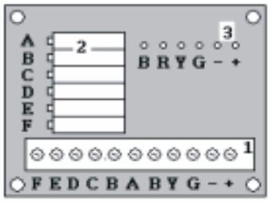
The calibration card is in the indicator housing.
It is simple to calibrate the load sensors using the load sensors’ calibration card. The four potentiometers are located on the circuit card and are labelled A, B, C, D. Each potentiometer is used to calibrate the corresponding load sensor. Turn the potentiometer clockwise to increase the load sensor’s indication. Turn the potentiometer anticlockwise to reduce the indication.
Order number Date Valid from serial number T-code
232020-040 2006-06-19 3 300 000- 805, 813, 830
5.2 Calibration example
You cannot calibrate the load sensors by turning a potentiometer while looking at the display to achieve the correct indication. When a potentiometer is adjusted, this affects all the load sensors. So do as follows:
If you have inspected the load sensors and concluded that load sensors A and C are showing +2 kg too much: Unload the system and adjust the value using the potentiometers. If the value to be adjusted is too high, turn the potentiometer anticlockwise to correct. Then check all corners again (with your own weight) and see whether the correction has made any difference. If not, repeat. It can take 5 to 10 attempts before all the values are optimised.
It is not vital for your exact weight to be shown in the display in this situation. What is essential is for the 4 values to be identical. Once the values are the same, the scale must be recalibrated as per the instructions in the calibration manual. 5.3 IMPORTANT: Calibration of a newly-fitted load sensor
When fitting a new load sensor, or when a calibration has resulted in a large difference in the values, it is best to start again.
Use an ohmmeter (voltmeter) and set 5 ohms between point R and the connection screws A, B, C and D (behind the potentiometer, see drawing). Once all the potentiometers have been set to 5 ohms, you can turn them to correct any reading error.
The indicator must be calibrated after calibrating the load sensors. See the calibration instructions.
T-code Valid from serial number Date Order number
805, 813, 830 3 300 000- 2006-06-19 232020-040
6. Checking the indicator
Warning!
Do not touch the circuit card’s contacts. Static electricity can damage the card components.
A common cause of faults affecting mobile weighing system is collisions and hard knocks. Remember this when tracing faults in the indicator housing and on the circuit card. Don’t be afraid to check the indicator by hitting it. This is the only way of detecting problems that occur during use of the system. It may even reveal hidden faults! 6.1 Checking the fuses
There is an electrical fuse in the indicator housing. Remeasure the fuse using an ohmmeter/voltmeter. 6.2 Checking the individual parts
Remove the circuit card from the indicator and check whether everything seems OK, whether any of the components are loose or whether bending the card solves the problem. 6.3 Checking whether the connections are disconnected or loose
It is essential that the cables to the power switch, fuse holder and contact are not loose. 6.4 Checking for possible moisture problems if the reading is unstable
Check whether there is any condensation or drops of water on the contacts. Look carefully for signs of this on the circuit card when the cover plate is removed and the contact disconnected from the indicator. Dry the card using hot air. If there is oxidation on the card, you can carefully solder the area around the analogue circuit using a soldering iron. 6.5 If the display reading is unstable or does not react to weights, you should check whether the indicator is causing the problem
Disconnect the indicator from the load sensors. If the indicator displays an error message: Connect each load sensor individually. If the indication is still unstable or does not react to the different load sensors, it is likely that the indicator module is defective. 6.6 When can you be sure that the indicator’s circuit card is defective?
The display is defective if: -the reading does not change when the load sensors are disconnected; -no lights come on with +12 V DC on the correct terminals and the keypad is working; -the reading remains unstable when only one load sensor is connected (try a new load sensor for confirmation); -the reading is affected when the indicator module is subjected to a knock.
Order number Date Valid from serial number T-code
232020-040 2006-06-19 3 300 000- 805, 813, 830
6.7 Checking the touch screen
Check the flat cable. The silver coating is conductive, but very thin.
Wear in just a small area can cause the touch screen to malfunction.
The flat cable’s contact is highly sensitive to moisture. Check the contact. If it has been affected by moisture, this can be remedied by heating the components for a prolonged period. 6.8 Checking the indicator’s LCD display
By gently flexing the circuit card in various directions while the display is active, you can locate broken contact points.
T-code Valid from serial number Date Order number
805, 813, 830 3 300 000- 2006-06-19 232020-040
This page is intentionally left blank


