1 minute read
7.2 Function


T-code Valid from serial number Date Order number
805, 813, 830 3 300 000- 2006-06-19 232020-040
The scale’s electronics card is powered by a 12 V battery.
The indicator is connected by 4 wires to each load sensor. The red and black wires supply power to the load sensor as a holding current. Each load sensor contains a resistor that acts as a strain gauge. As soon as any weight is placed on the load sensor, the sensor is distorted, resulting in a change in the resistor in the strain gauge, and, consequently, a change in the output voltage.

Order number Date Valid from serial number T-code
232020-040 2006-06-19 3 300 000- 805, 813, 830
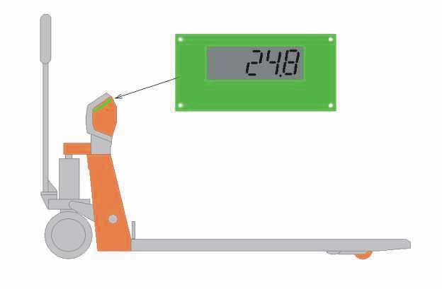
The load sensor’s output voltage is a signal that is proportional to the weight, and is transmitted back to the indicator via the green and white wires. The indicator functions as a voltmeter or ohmmeter. Changes in the signal level are measured and converted into a weight value. Calibrating the scale programs the load sensor with an output voltage corresponding to weights of 0 kg, 200 kg, 500 kg and 2000 kg. The calibration data is stored in an EEPROM circuit on the card, and this data is used by the indicator until the system is recalibrated.
There is a calibration card between the indicator and load sensors. By adjusting the input voltage from the various load sensors using potentiometers it is possible to fine-tune the four corners of the ‘scale’ in relation to one another.


