Portable Pressure Washer Familiarization and Troubleshooting Guide Section 6 • Medium Frame Pump
Part 4 - Reassembly
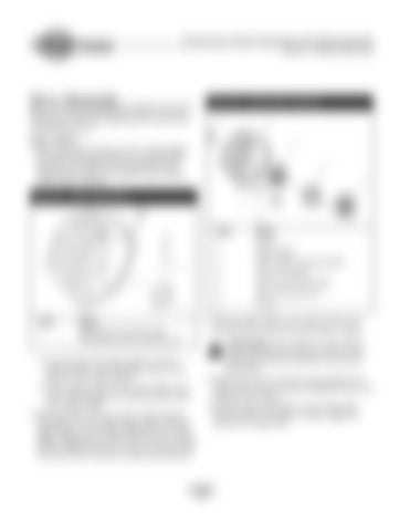
Figure 6.22 — Engine Adapter Components
Refer to the Torque Specifications provided on the pump exploded view found at the beginning of this section when reassembling this pump. Engine Adapter 1. Early medium frame pumps may have an engine adapter pilot sleeve. Referring to Figure 6.21, apply LOCTITE Permabond No. HM160 to the outside of the larger diameter of the sleeve, then install the sleeve into the engine adapter as follows: Figure 6.21 — Engine Adapter Sleeve
Item
Name
1
Apply Loctite around the larger circumference of the ring in this area.
Item
Name
1
O-ring
2
Engine adapter
3
Engine adapter bearing assembly
4
Axial cam assembly
5
Axial cam bearing assembly
6
Button head cap screw
7
O-ring
3. Retain the engine adapter to the engine with four (4) 5/16”-24x 3/4” screws and four (4) o-rings or washers.
CAUTION: When installing the engine adapter having the O-Ring seals, be sure to use the correct button head cap screws. DO NOT use any other type fastener.
a. From the inside of the engine adapter, press the smaller-diameter end of the adapter sleeve into the large bore of the engine adapter.
4. Tighten the screws to the torque value specified in the Torque Chart, found on Figure 6.2 (Exploded View) at the beginning of this chapter.
b. Tap the adapter sleeve into the engine adapter bore until it seats flush against the inside machined surface of the engine adapter.
5. Install the engine shaft adapter over the engine shaft, ensuring the key in the axial cam adapter engages the keyway on the engine shaft.
2. Referring to Figure 6.22, use a new o-ring around the housing pilot or a new engine adapter gasket. Install the engine adapter onto the engine. Note that newer engine adapter castings have the word ‘TOP’ cast into it. The oil breather designates the ‘top’ of the pump crankcase. Both ‘top’ sides must be matched for proper pump operation.
64
