7 minute read
Vibration system

from Bomag BW 145 D-3 DH-3 PDH-3 Single Drum Rollers Service Training Manual 00809955 - PDF DOWNLOAD

The vibration system of the single drum rollers BW 145 of generation 3 works with two amplitudes. This enables perfect adaptation of the machine to various types of soil and different applications.
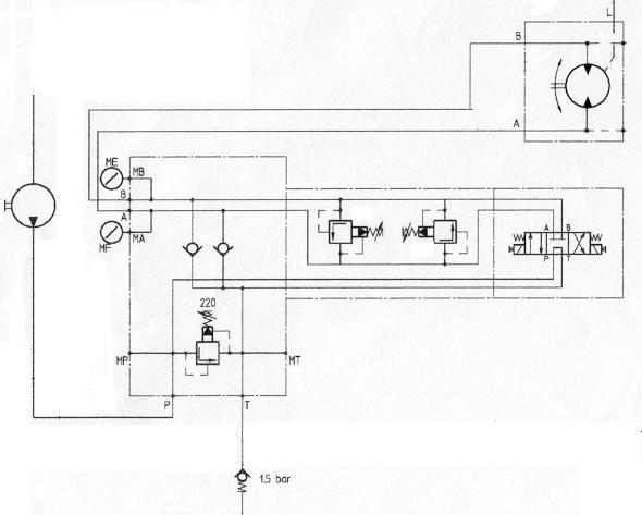
The vibration drive is an open hydraulic circuit. The circuit consists of:
•the vibration pump,
•the vibration control valve with integrated safety elements,
•the pressure resistant connecting hoses.
•and the vibration motor
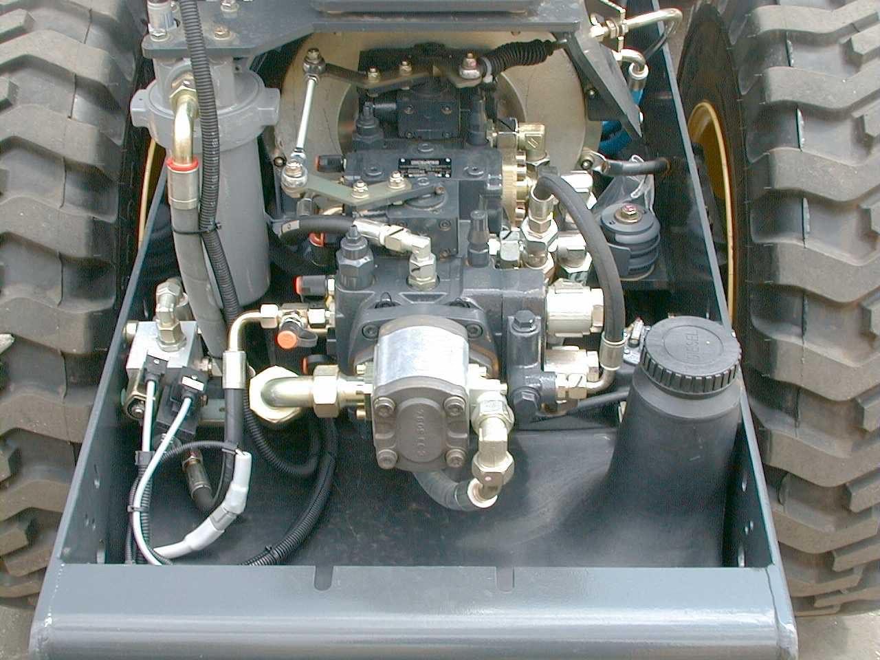
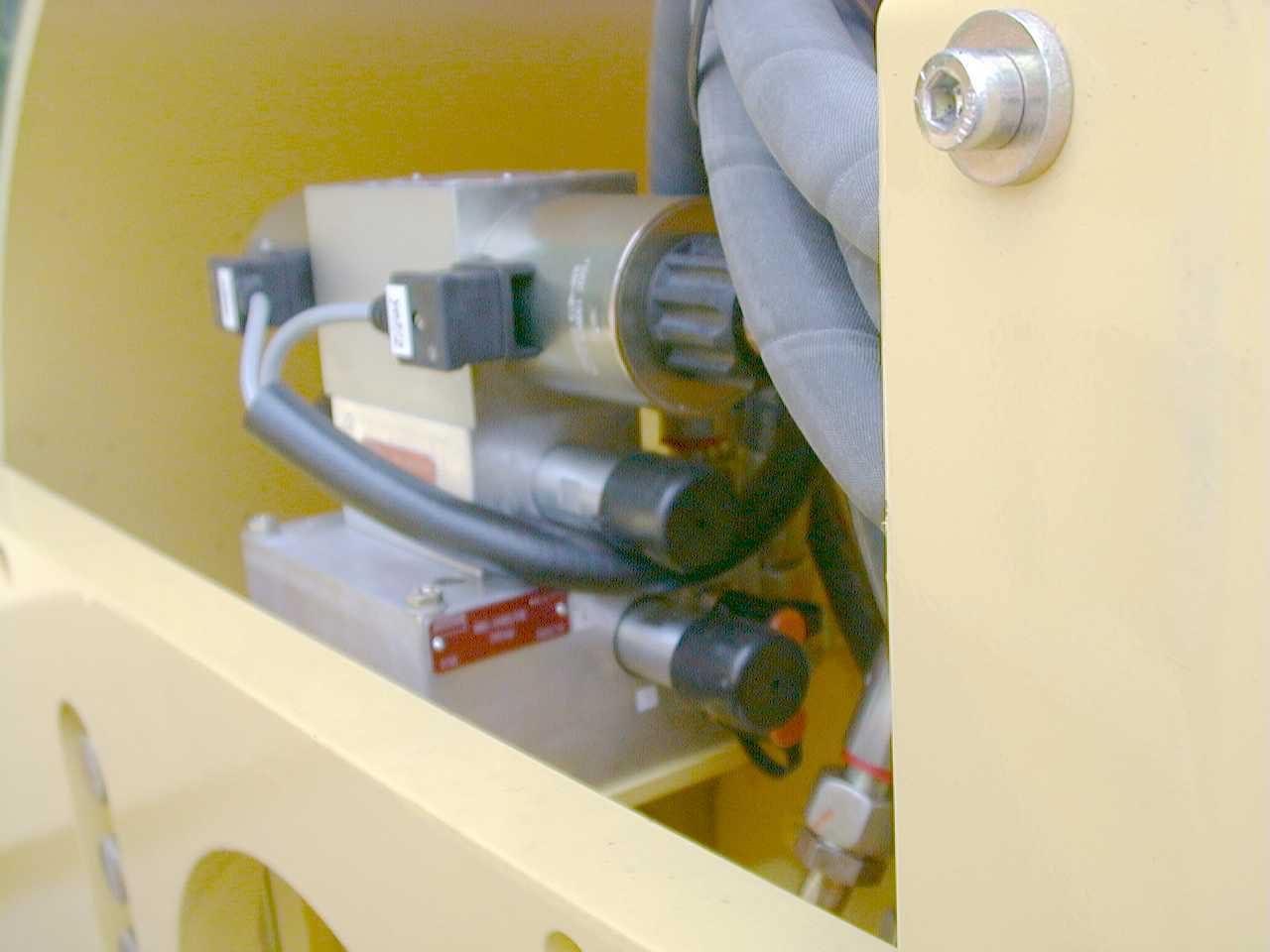
1Vibration pump
2Vibration control valve with integrated safety elements
2Vibration motor
Vibration pump and travel pump are joined together to a tandem or triple pump unit. This unit is directly driven by the diesel engine.
The vibration pump is a gear pump and therefore delivers a permanent oil flow, as soon as the engine is running. In neutral position of the vibration control valve the complete oil flow is directed through the vibration control valve back to the tank. When actuating the 4/3-way solenoid valve on the vibration control valve out of neutral to one of the two possible positions, oil is delivered to the vibration motor. The vibration motor starts and rotates the vibrator shaft inside the drum.
Depending on the switching position of the vibration control valve the oil is delivered to inlet ports A or B on the vibration motor. This results in two different directions of rotation of the exciter shaft.
The eccentric weights on the vibrator shaft are fitted with additional change-over weights. Depending on the sense of rotation of the vibrator shaft these change-over weights add to or subtract from the basic weights.
This results in the following constellations:
• Basic weight + change-over weight = high amplitude
• Basic weight - change-over weight = low amplitude
After the oil has left the vibration motor it flows back through the vibration control valve to the tank. The tank is equipped with an upstream 1.5 bar pressure relief valve.
When switching the vibration off the vibration motor for a short moment works as a pump, because the kinetic energy of the exciter shaft must first be eliminated. This energy is relieved through the respective secondary high pressure relief valve /220 bar) inside the vibration control valve. In order to avoid cavitation, the respective low pressure side of the vibration motor is connected with an anti-cavitation valve inside the vibration control valve. The anti-cavitation valves then deliver oil from the 1.5 bar preloaded pump flow back to the tank.
Vibration pump
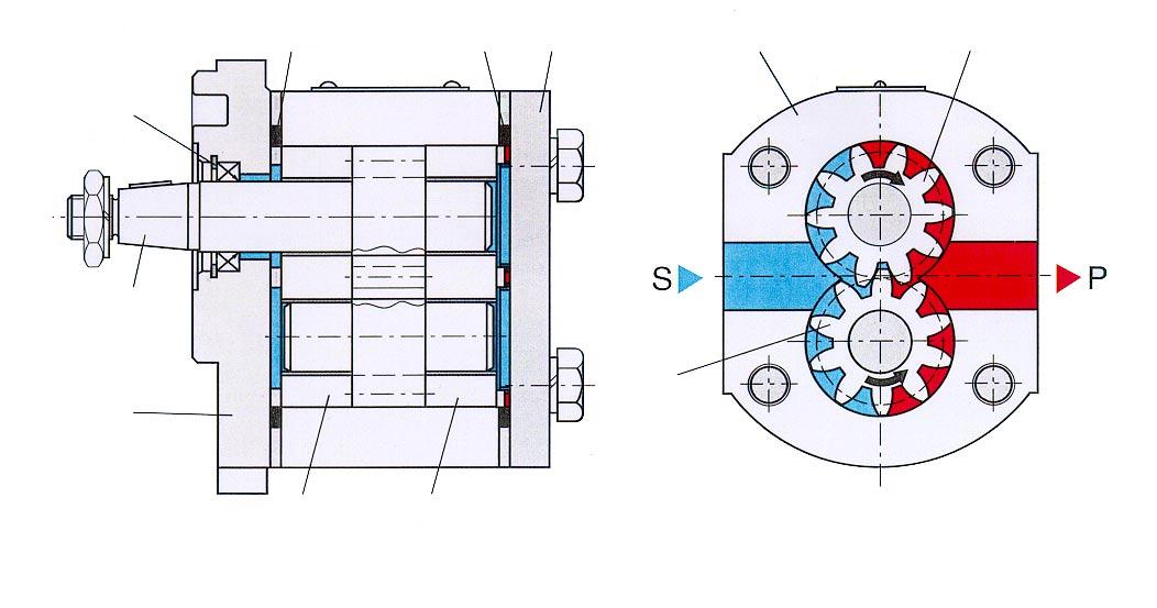
The vibration pump is a gear pump with fixed displacement.
The pump flow rate is proportional to the engine speed.
The pump is mounted to the back of the travel pump unit and is driven by the diesel engine via a mechanical through-drive. The pump draws the hydraulic oil from the hydraulic oil tank.
Function of the gear pump
Drive gear and driven gear are positioned by a bearing plate in such a way, that the teeth of both gears mesh with minimum clearance when rotating.
The displacement chambers are formed between the tooth flanks, the inside wall of the housing and the faces of the bearing plates. The chambers transport the hydraulic oil from the suction side to the pressure side. This generates a vacuum in the suction line, which draws the hydraulic oil out of the tank. These tooth chambers transport the hydraulic oil along the inside wall of the housing from the suction side to the pressure side, from where it is pressed to the consumers. To ensure a safe function of the pump the tooth chambers must be so tightly sealed that the hydraulic fluid can be transported from the suction side to the pressure side without any losses.
Outer gear pumps are provided with gap seals. This results in pressure level dependent fluid losses from the pressure side to the suction side. An axial pressure field presses the bearing plate on the cover side against the front face of the gears, making sure that only a very little quantity of oil will leak from the pressure side to the suction side when the pressure increases during operation.
The pressure field is always under system pressure.
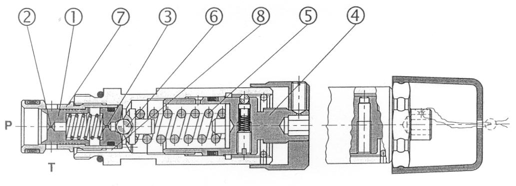
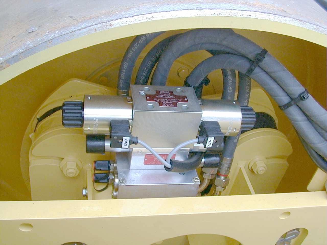
Vibration control valve
The vibration control valve contains the following functions:
• Vibration on and off
• Changeover of amplitude
• Pressure limitation (primary and secondary side).
14/3-way
2Secondary pressure relief valve5Test port for high amplitude
3Primary pressure relief valve6Test port for low amplitude
7Outlets to the vibration motor
When the engine is running the full flow volume from the vibration pump is permanently applied to port P of the vibration control valve. As long as the vibration is switched off the spool of the 4/3-way solenoid valve is in neutral position. In this position the complete flow volume flows through the internal connection in the valve back to the tank.
When switching the vibration on, one of the solenoids (depending on the selected amplitude) is supplied with 12 V, the spool of the 4/3-way valve moves to the corresponding position, the vibration starts. Since the exciter shaft has to overcome its moment of inertia during the acceleration process, a so-called vibration start-up pressure wilol build up for a short moment, which is limited by the promary pressure relief valve in the control valve block.
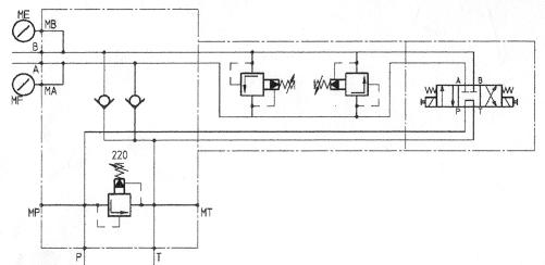
When switching the vibration off the vibration motor for a short moment works as a pump, because the kinetic energy of the exciter shaft must first be eliminated. Depending on the sense of rotation this energy is relieved through the respective secondary high pressure relief valve (220 bar) inside the vibration control valve. In order to avoid cavitation, the respective low pressure side of the vibration motor is connected with an anti-cavitation valve inside the vibration control valve. The anti-cavitation valves then deliver oil from the 1.5 bar pre-loaded pump flow back to the tank.
1 Solenoid valve Y08
2 Solenoid valve Y07
3 Secondary pressure relief valve
4 Secondary pressure relief valve
5 Outlet A, low amplitude
6 Outlet B, high amplitude
7 Output T, to tank pre-load valve
8 Input P, from vibration pump
9 Primary pressure relief valve
10 Test port for test connection MP
11 Test port for test connection MP
12 Pressure test port MB, high amplitude
13 Pressure test port MA, low amplitude
14 Anti-cavitation valves
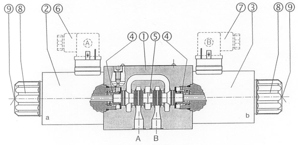
1Valve housing
2Magnetic coil
3Magnetic coil
4Centring springs
5Control piston
6Plug
7Plug
8Fastening nut
9Emergency operation (only with special control pin)
The valve spool geometry is designed in such a way that P and T are joined in neutral position and that all channels are connected when switched.
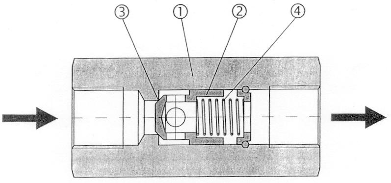
Pressure relief valves
1Control piston
2Nozzle
3Nozzle
4Setscrew
5 Spring
6Ball, pilot control valve
7Bushing
8Groove
The pressure relief valves on primary and secondary side are similar in design and pressure setting. These valves are pilot controlled pressure relief valves. The primary valve limits the vibration start-up pressure, the secondary valve protects the system against overpressure when switching the vibration off.
The pressures are adjusted by the setscrew (Fig. 4, Pos. 4). If no pressure is applied the valve is closed. Pressure is applied to the front face of the control piston (Pos.1) and, at the same time, through nozzle (Pos. 2) on its spring loaded back and also through nozzle (Pos. 5). on the ball (Pos. 6) of the pilot control valve.
When the increasing pressure reaches the value determined by spring (Pos.5), the pilot control valve will open and the pilot oil flow is released. The spring loaded side of the control piston is relieved, the function edge of the control piston opens the radially arranged bores in the bushing (Pos. 7) and the oil flows from P to T. The pilot oil is discharged through the groove (Pos.8) to port T.
Anti-cavitation valves
1Housing
2Cone
3Valve seat
4 Spring
The anti-cavitation valves are fixed spring loaded check valves, which protect the low pressure side against cavitation when switching the vibration off.
Vibration motor
The vibration motor is a swash plate type axial piston motor with fixed displacement of series MMF 025 from Sauer-Sundstrand. Since the motor is designed for pressure application from both sides, it is most suitable for closed circuit installation and alternating loads.
The output speed of the motor depends on the oil quantity supplied by the vibration pump. As this oil quantity solely depends on the engine speed, the exciter frequency also depends on the engine speed.
2Flushing valve8Swash plate
3Cylinder block9Retaining plate
4Pistons with slipper pads10Pre-loading spring
5Roller bearing for output shaft11Flushing pressure relief valve
6Radial seal
When switching the vibration on the motor must first accelerate the resting vibration shaft up to maximum speed. This resistance causes a hydraulic starting pressure, which is limited to 220 bar by the primary high pressure relief valve inside the vibration control valve. Once the vibrator shaft has reached its final speed, the pressure will drop to a value between 45 and 65 bar (operating pressure). This pressure mainly depends on the condition of the soil (degree of compaction, material etc.).
• Hard ground = high operating pressure
• Loose ground = low operating pressure
After the oil has left the vibration motor it flows back through the vibration control valve to the tank. The tank is equipped with an upstream 1.5 bar pressure relief valve.
When switching the vibration off the vibration motor for a short moment works as a pump, because the kinetic energy of the exciter shaft must first be eliminated. This energy is relieved through the respective secondary high pressure relief valve /220 bar) inside the vibration control valve. In order to avoid cavitation, the respective low pressure side of the vibration motor is connected with an anti-cavitation valve inside the vibration control valve. The anti-cavitation valves then deliver oil from the 1.5 bar preloaded pump flow back to the tank.
1Drum shell7Travel bearing
2Vibration bearing housing8Travel bearing housing
3Basic weight9Rubber buffer
4Vibrator shaft10Vibration motor
5Change-over weight11Flanged housing
6Coupling vibr.-motor – vibrator shaft
Test and adjustment points in vibration system
Trouble shooting
The following trouble shooting chart contains a small selection of possible faults, which may occur during operation of the machine. The fault list is by no means complete, however, the fault table is based on the experience of the central service department, i.e. the list covers almost all faults that have occurred in the past.
Procedure:
The following trouble shooting table contains both electrical as well as mechanical and hydraulic faults. The number specified in the table indicate the probability of the fault cause and thereby the recommended trouble shooting sequence, based on our latest field experience.
Troubleshooting Vibration
BW145-3-FAMILY
Possiblecauses
Vibrationswitchr(Amplitudeselectorswitch)21
Vibrationbutton(on/off)1
Wiring12 Vibrationvalvesolenoidsdefctive,valvedirty/sticky212
Vibrationpumpedefective33
Couplingbetweentravelpumpandvibrationpumpdefective3
Vibrationvalvedefective3
Vibrationmotorcouplingdefective22
Vibrationmotordefective33
Dieselenginespeed1