3 minute read
Service Training

from Bomag BW 145 D-3 DH-3 PDH-3 Single Drum Rollers Service Training Manual 00809955 - PDF DOWNLOAD

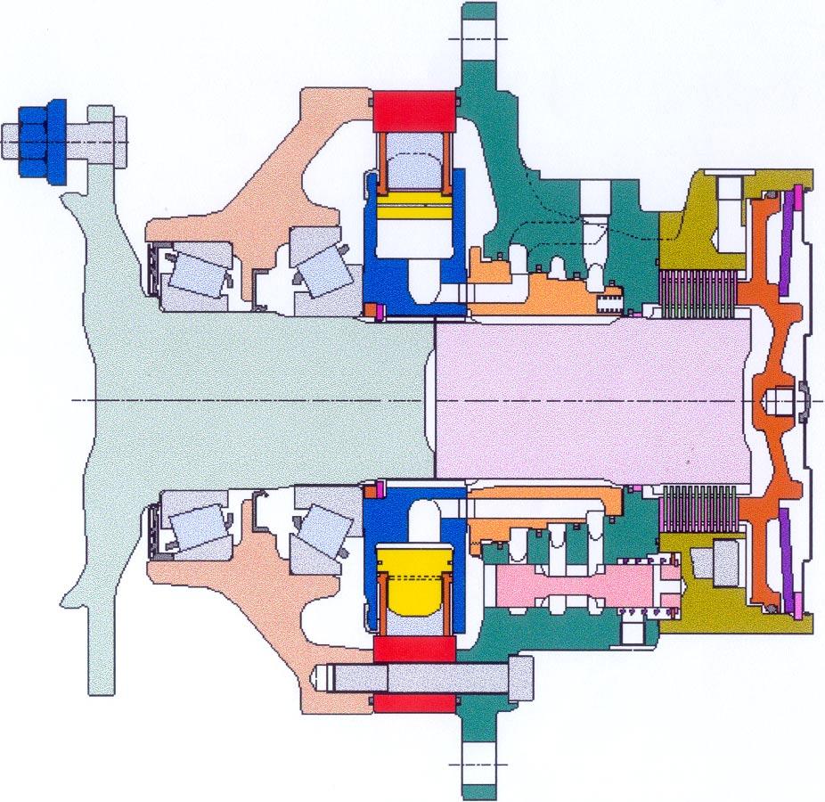
Drum drive motor
On all single drum rollers of series BW 145 D-3/ DH-3 / PDH-3 the front drum is driven by a hydraulic radial piston motor. On the DH / PDH models these motors are designed for two speed ranges (half displacement = 2nd gear), on the D model the motor is designed with a fixed displacement.
2Tapered roller bearing9Brake discs
3Bearing plate10Brake housing with brake connection
4Cam race11Brake piston
5Working pistons12Brake spring
6Cylinder block13Piston, speed range selection (only DH/PDH models)
The housing consists of:
• brake housing
• oil distributor.
• torque module (cam race) and
• bearing plate (bearing for output shaft),
Pressure oil flows through the flat distributor to the working pistons in the cylinder block. This pressure oil presses the working pistons with the rollers against the cam race of the torque section and forces the rollers to roll along the cam race.
During this process the axial movement of the pistons is converted to a radial movement of the cylinder block. The cylinder block transfers this rotation via a splined connection to the output shaft.
The output shaft runs in two tapered roller bearings. It transfers the rotational movement via drive disc and rubber elements to the drum.
The function of the radial piston motor is described hereunder. The piston positions described in this explanation can be seen in the related illustration.
Fig. 12 Function of the radial piston motor
The movement of a piston along the cam race must be examined in several phases during a full rotation:
Piston position 1:
The oil enters into the oil distributor under pressure, flows through the distributor and presses against the piston. This is the start of a rotation. The pressure applied to the back of the piston moves the roller along the cam and causes a rotation of the cylinder block.
Piston position 2:
At this point the opening cross-section for the oil flow to the piston has reached its maximum size. The piston continues his travel along the cam race towards the valley between two cams. As the rotation progresses the opening cross section for the oil supply becomes smaller and smaller.
Piston position 3:
Once the piston has reached the bottom of the valley, the oil flow to the piston is interrupted. The piston is no longer driven. It has reached its dead centre. Now another piston must be driven to move the first piston out of the dead centre.
Piston position 4:
Other driven pistons now move the first piston out of the dead centre. The oil behind the piston is now connected with the low pressure side and the reverse movement of the piston presses the oil back to the pump.
Piston position 5:
The pumping movement of the motor back to the pump comes to an end, the connecting bore between cylinder chamber and low pressure side slowly closes again. The piston reaches its second dead centre position. This point is the start of a new working cycle.
Reversing the oil flow reverses also the rotation of the motor.
The output shaft is resting in two taper roller bearings. It transmits the rotational movement via drive disc and rubber elements to the drum.
Travel motor (axle)
All single drum rollers of series BW 145-D-3 / DH-3 / PDH-3 from construction date around 06/2002 (S/ N see technical data) are equipped with hydraulic axial piston motors A10VM 63 EZ for the rear wheel drive.
The high pressure sections of this motor are directly connected to the travel pump.
from brake valve 2 6
4 5
7 8
1Axle with brake5 Flushing valve
2Variable displacement motor6Control piston
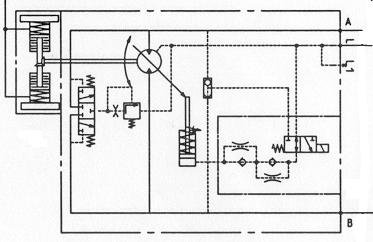
3Speed range selector valvewith control solenoid7Shuttle valve
3
4Flushing pressure relief valve8Switching delay nozzles
The pressure oil from the pump flows through the respective motor inlet to the back of the working pistons. Since the working pistons are arranged under a certain angle to the axis of the motor, the pressure oil causes and axial movement of the working pistons. The axial movement of the working pistons is transferred to a radial movement of the cylinder block in the motor housing.
Once a piston reaches its top dead centre (max. extension position), it changes over to the low pressure side of the closed circuit. The retaining plate pulls the piston back into the rotating cylinder block, thereby pressing the hydraulic oil through the motor outlet back to the pump.
The displacement and thereby the swashing angle is limited to both sides (Qmin and Q max) by setscrews. These setscrews are correctly adjusted in the factory and do n ot need to be adjusted when using original BOMAG motors for replacement. However, if the setscrews have been deadjusted by mistake, the setscrews must be exactly adjusted as shown in Fig. 13 especially on DH / PDH machines (double pump drive), to avoid one travel circuit blocking the other.
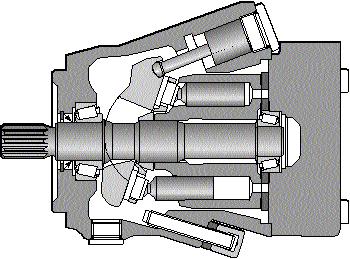
The Qmin screw directly limits the swashing angle of the swash plate, the Qmax screw limits the maximum stroke of the control piston.
Measurement X on Qmax-screw: for all 145-3 types with A10 motor:
14.3 mm = 57.0 ccm
Measurement X on Qmin-screw: for all 145-3 types with A10 motor:
12.7 mm = 28.5 ccm