7 minute read
Service Training

from Bomag BW 145 D-3 DH-3 PDH-3 Single Drum Rollers Service Training Manual 00809955 - PDF DOWNLOAD

Travel pump(s)
The travel pump on the BW 145 D-3 is a swash plate actuated variable displacement axial piston pump from Hydromatik, type A10VG 63 HWD.
The tandem pump unit used on the models BW 145 DH-3 / PDH-3 consists of two variable displacement axial piston pumps of the same type A10VG 28 HW. The pumps are fitted with all control and safety elements needed for operation in a closed hydraulic circuit. These are:
• Servo control
• High pressure relief valves with integrated boost check valves
• Charge pressure relief valve
• Pressure override to the tank thermostat to cross-flushing drum drive
Charge oil to brake valve to/from travel motors from/to travel motors
1Variable displacement pump2Servo valve (mech. control)
3Control piston6Feedback lever
5High pressure relief valves6Boost check valves
7Pressure override8Charge pressure relief valve
Travel pump(s) and vibration pump are connected to a tandem unit (D-3)or a triple pump unit (DH-3 / PDH -3).
The travel pump unit is directly driven by the flywheel end of the diesel engine via an elastic coupling. The pump speed is therefore identical with the engine speed.
The spherical valve plate centres cylinder block, which is mounted on the splines of the drive shaft. This avoids the appearance of undesired transverse forces.
The complete drive consisting of
• valve plate
• cylinder block with working pistons and
• swash plate is preloaded by a pressure spring. This immediately eliminates any appearing wear, increases the efficiency of the pump and considerably prolongs the lifetime of the pump.
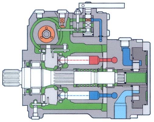
1Drive shaft9Valve plate
2Roller bearing10Charge pump (not for BOMAG)
3Swashing bearing11Control unit
4Swashing cradle12Setscrew for hydraulic neutral position
5Slipper pads13Feedback lever
6Working pistons14Control piston
7Cylinder block15Sliding block
8Pressure spring
Pilot pressure is used to operate the pump out of neutral position to the desired pumping direction (direction of oil flow).
A manually operated 4/3-way valve directs the pilot oil flow (from the charge circuit) to the corresponding control piston side in the servo control. The 4/3-way valve is actuated by the travel lever and the travel control cable.
In neutral position both control chambers are loaded with case pressure. When opening the 4/3-way valve pilot oil (from the charge circuit) is directed to one of the control piston sides and moves the control piston to the corresponding direction.
The swashing lever between the control piston and the swash plate transfers the control piston movement to the swashing cradle. The needle bearing mounted swash plate swivels to the chosen direction. This causes the axial movement of the pistons inside the cylinder block. The axial movement draws oil into the pump and presses it to the travel motors.
All working pistons are drilled through their entire length. Pressure fluid flows through these bores into the areas between the slipper pads and the surface of the swashing cradle. This forms a hydraulically balanced field, on which the slipper pads can slide without any metal-to-metal contact between swashing cradle and slipper pads. The feedback lever on the control piston detects when the swashing cradle has reached a position that corresponds with the displacement of the travel lever. This feedback lever controls a pilot oil dosing valve which interrupts the pilot oil flow to the control chambers when the swashing angle corresponds with the position of the travel lever. Swashing angle and displacement of the working pistons (oil flow rate) remain constant, until a new control command requires a different swashing angle.
When changing the swashing angle through the neutral position to the opposite side, the flow direction of the oil and the sense of rotation of the travel motors will change.
When controlling the travel pump pressure will build up in the line between pump outlet and motor inlet. This pressure depends on the load acting on the travel motors. This pressure keeps the boost check valve inside the high pressure relief valve for this particular side of the closed hydraulic circuit closed.
Cool and filtered oil can now only enter into the closed circuit on the opposite side (low pressure side). The high pressure relief valve limits possibly occurring extreme pressure peaks to the adjusted value. If one of these valves responds, hydraulic oil will flow out of the high pressure side and enter the low pressure side through the corresponding boost check valve.
Since the cross-sections of these valves are very small and the hydraulic oil enters the low pressure side already inside the pump, the system would very quickly overheat if the pressure in the system would be permanently relieved via the high pressure relief valves. For this reason the pump is fitted with an additional pressure override valve. The pressure override valve interrupts the pilot oil flow to the control piston, thereby maintaining the pressure level at the adjusted value of the pressure override valve. If the pressure drops again, the pressure override valve will open and the pump can swash back to the previously chosen position. This installation prevents overheating of the hydraulic system and overloading of the diesel engine.
Control
The servo control of the pump is an integral part of the pump housing and consists mainly of:
• the manually controlled proportional 4/3-way valve
• the control piston
• the feedback lever
• the pilot oil dosing valve
• the swashing cradle with swashing lever to – from motors
When operating the travel lever the 4/3-way valve will move out of neutral position to the desired direction, thereby guiding the pilot oil flow to the corresponding control piston side. The control piston moves to the corresponding direction and operates the swashing cradle accordingly via the swashing lever.
The feedback lever, which is mounted with its ball head in the pump control shaft, follows the control piston and interrupts the pilot oil flow when the control piston has reached a position corresponding with the displacement of the travel lever. The pump can now deliver oil to the travel motors.
The oil from the opposite control chamber flows through the 4/3-way valve as leak oil into the pump housing.
The supply bores for both control chambers are fitted with nozzles (swashing time nozzles). These nozzles restrict the pilot oil flow and enable very sensitive controlling of the pump.
The feedback lever controls the pilot oil rating valve so that the swashing angle remains unchanged, until a new control command is triggered.
Fig. 6 Control actuated
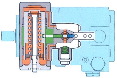
from the charge pump 4/3-way valve > < > < 1 2
When the 4/3-way valve is in neutral position, the pressure values in both control chambers are identical (case pressure = max. 3 bar).
Leak oil Travel pump Control piston 3 4
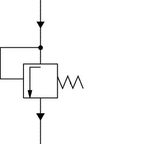
Charge pressure relief valves
The charge pressure relief valve belongs to the group of safety elements in a closed hydraulic circuit. This valve limits the pressure in the charge circuit to the adjusted value.
The DH/PDH-versions are fitted with a charge pressure relief valve in each travel pump.
Pressure oil from filter
Charge pressure
7 Charge pressure relief valve
fixed spring
The charge circuit is needed for the compensation of leak oil and flushing quantities in the closed hydraulic circuit. Charge oil is also needed for the pump control, for speed range selection in the axle drive motor and for releasing the parking brake.
Since feeding of cool and filtered oil is only possible on the low pressure side of the closed circuit, the pressure in the low pressure side is identical with charge pressure. If the travel pump is in neutral position, both boost check valves can open and let in oil from the charge circuit. In this case the pressure in both sides of the closed circuit is identical with charge pressure.
High pressure relief valves
High pressure relief valves are safety elements, which are needed in every hydraulic circuit. These valves limit the pressure in the hydraulic circuit to the value determined by the adjustment spring.
The high pressure relief valves in both sides of the hydraulic circuit protect the hydraulic system, the diesel engine and all other machine components against overloads.
1Travel pump
2Control piston (actuated)
34/3-way valve (actuated)
4High pressure relief valves
The boost check valves are integrated in the high pressure relief valves. These valves open to the low pressure side and allow cool and filtered oil flow from the charge oil circuit to flow into the closed hydraulic circuit, in order to compensate leaks and flushing quantities.
Pressure override
Since the cross-sections of the high pressure relief valves are very small, longer responding of these valves would cause very quick overloading of the hydraulic circuit and would subsequently lead to severe damage in pump or other components. In order to avoid this, the travel pump is equipped with another safety device, the pressure override.
Fig. 9 Pressure override
1Charge pump
2Pressure override
3Travel pump
4Control piston
53/4-way valve
6Shuttle valve
The pressure override is hydraulically arranged in the pilot oil flow to the pump control before the 4/3way valve and consists off:
• axial spool with control edges,
• adjustment spring and
• setscrew with counter nut.
The shuttle valve always connects the spool in the pressure override with the highest pressure in the closed circuit. As long as the pressure in the closed circuit is lower than the setting of the pressure override, the pilot oil flow to the corresponding control chamber is enabled through the 4/3-way valve. The pump can now be actuated up to maximum displacement.
If the pressure reaches the setting of the pressure override, the spool inside the valve will move and cut off the pilot oil flow to the control piston. The pump cannot be actuated any further. The system pressure is maintained at the setting of the pressure override, until the resistance causing this high pressure in the system is overcome or the operator actuates the pump back to neutral position.
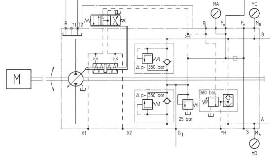
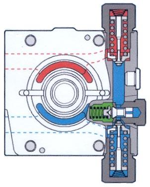
1High pressure relief valves
2Charge pressure relief valve
3Pressure override
Should the pressure in the closed circuit drop below the setting of the pressure override, the valve spool will be forced back by spring force, whereby the passage between charge circuit and pump control is opened again. Now pilot oil can flow to the corresponding control piston side again and the pump can be actuated.
The spring force of the pressure override and its reaction value can be adjusted via the adjustment screw.
Due to the construction and the hydraulic arrangement of the pressure override the high pressure relief valves will not respond. This type of pressure limitation does not release any oil from the closed circuit through the very narrow cross-sections in the high pressure relief valves. This avoids overheating of the hydraulic oil.
In order to ensure a safe function, the setting of the pressure override should always be approx. 10% lower than the setting of the high pressure relief valves.
High pressure relief valve ∆p= 380 bar, i.e. approx. 405 bar absolute pressure (the charge pressure of 25 bar must be added to the 380 bar)
Pressure override 380 bar