5 minute read
FINAL DRIVE CASE


Checking Oil Level
Put the machine on a flat level surface with the plugs positioned as shown in figure [A]
Remove the top plug (Item 1) [A]. The oil level should be at the bottom edge of the plug hole.
Add gear lube 90W through the hole if the oil level is below the hole. (See Fuel, Coolant and Lubricant Chart, Page 52.)
Install and tighten the plug.
Repeat the procedure for the other side.
Draining Final Drive Case
See the SERVICE SCHEDULE Page 27 for the correct service interval.
Put the machine on flat level surface with the plugs positioned as shown in figure [A].
Remove the bottom plug (Item 2) [A] and top plug (Item 1) [A]
After all the gear lube is removed, install and tighten the bottom plug (Item 2) [A]
Add .55 quarts (0,5 L) of gear lube 90W to the top plug hole (or until gear lube level is at the bottom edge of the plug hole). Install the plug.
Repeat the procedure for the other side.
Track Tension
NOTE:The wear of the pins and bushings on the undercarriage vary with the working conditions and the different types of soil conditions. It is necessary to inspect track tension to maintain the correct tension. See SERVICE SCHEDULE Page 27 for the correct service interval.
Adjustment
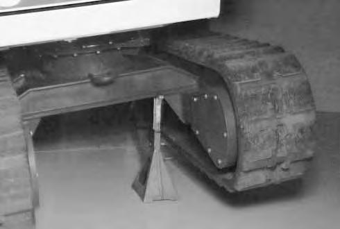
Raise the machine using the boom and arm [A]
Raise the blade and install jackstands under the blade and swing frame [A] and [B]. Lower the boom until all machine weight rest on the jackstands.

Stop the engine.
Avoid Injury Or Death
Keep fingers and hands out of pinch points when checking the track tension.
W–2142–0189
Rubber Tracks
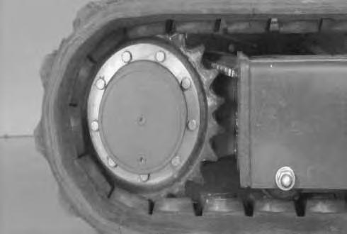
Measure the rubber track sag at the middle track roller [C]. Do Not get fingers into pinch points between the track and the track roller. Use a bolt or a dowel of the appropriate size to check the gap between the contact edge of the roller and the top edge of the track guide lug [C] and [D]
TRACK TENSION (Cont’d) Steel Tracks
Measure the steel track sag at the center of the track, between the lower edge of the track frame and the top surface of the track [A]
Steel Track Sag4.25 – 4.75 inches (108–120 mm ).
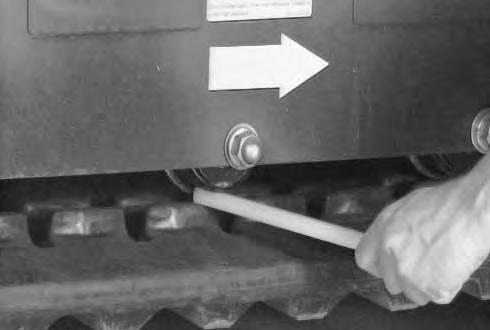
To adjust the track tension, do the following: Loosen the two bolts (Item 1) [B] from the cover. Pivot the cover downward.
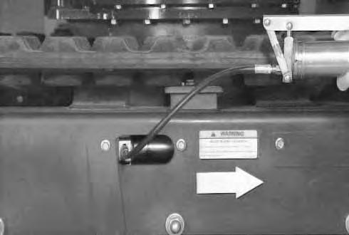
Add grease to the fitting (Item 1)[C] until the track tension is correct.
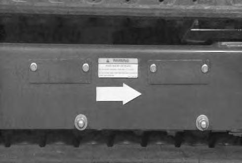
Loosen the bleed fitting (Item 1) [D] to release tension from the track.
NOTE:Do not loosen the grease fitting (Item 2) [D].

Repeat the procedure for the other side.
NOTE:Right hand side track frame grease fitting and bleed fitting are shown in photo [D]. For left hand side track frame, the grease fitting (Item 2) [D] will be on the bottom and bleed screw (Item 1) [D] will be on the top.
Joystick Control Change
To change from I.S.O. to STANDARD joystick controls, do the following procedure:
Remove the seat. See Service Manual.
Remove the center floor panel. (See Service Manual.)
Remove the swing motor cover and rear floor panel. (See Service Manual.)
Remove the left control panel base. (See Service Manual.)
To change I.S.O. to STANDARD control pattern do the following:
Mark the hoses on the end of each valvespool as shown [A].
Remove the boom control hoses (Item 1)[A] and the arm control hose (Item 2) [A] and relocate (switch) these hoses on the control valve [B]
Remove the arm control hose (Item 3) [A] and the boom control hose (Item 4) [A] and relocate (switch) these hoses on the control valve [B]
After the hoses have been switched, the hoses must be as shown [B]
The R.H. joystick will now control the arm (Arm out and Arm in) and the bucket curl.
The L.H. joystick will now control the arm (Boom up and Boom down) and the upper works swing.
Do not exchange any of the hoses on the top of the control valve to the work cylinders. Switch only the hoses that connect the joystick to the control valve spools.
Clean the existing decals on the control consoles with soap and water and dry.
Install the STANDARD control pattern decals (P/N 6589843 for R.H. console and P/N 6589842 for the L.H. console) on top of the existing control pattern decals.
To change STANDARD to I.S.O. control pattern do the following:
Mark the hoses on the end of each valvespool as shown [A].
Remove the arm control hose (Item 1) [C] and the boom control hose (Item 2) [C] and relocate these hoses on the control valve [D]
Remove the boom control hose (Item 3) [C] and the arm control hose (Item 4) [C] and relocate (switch) these hoses on the control valve [D].
After the hoses have been switched, the hoses must be as shown [D].
The R.H. joystick will now controlthe boom (Boom up and Boom down) and the bucket curl.
The L.H. joystick will now control the arm (Arm out and Arm in) and the upper works swing.
Do not exchange any of the hoses on the top of the control valve to the work cylinders. Switch only the hoses that connect the joystick to the control valve spools.
Clean the existing decals on the control consoles with soap and water and dry.
Install the I.S.O. control pattern decals (P/N 6589740 for R.H. console and P/N 6589741 for the L.H. console) on top of the existing control pattern decals.
Hydraulic Excavator Specifications
• All dimensions are shown in inches. Respective metric dimensions are given in millimeters enclosed by parentheses.
• Where applicable, specifications conform to SAE or ISO standards. Specifications are subject to change without notice.
Two joystick levers control boom, bucket, arm and swing. A separate lever controls blade. Left foot pedal controls auxiliary hydraulics. Right foot pedal controls boom swing.
SYSTEM Final Drive Each track is Independently Driven by a Hydrostatic Axial Piston Motor Type of Reduction Two Stage Planetary Gear Reduction
Crawler–Tractor Design Undercarriage. Sealed Track Roller W/ Reinforced Box–Section.
Track Roller Frame. Grease Type Track Adjusters W/Shock Absorbing Recoil Springs
Hydraulic Lock in Motor
FUEL, COOLANT AND LUBRICANTS
Use the following chart for correct selection of Fuel, Coolant and Lubricants.
* If Bobcat fluid (P/N 6563328) is not available, use Engine Oil SAE 10W–30/10W–40, Class SE.
Engine Oil Specifications
Description
When fuel sulphur content is less than 0.5% change the engine oil and filter as shown in the Service Schedule (Page 28).
Change engine oil and filter according to the following chart if fuel sulphur content is above 0.5%.
Fuel SulphurChange Interval Of ContentEngine & Oil Filter
0.5 to 1.0%1/2 of Regular Interval
Above 1.0%1/4 of Regular Interval
** COOLANT MIXTURE
Ethylene Glycol
Add premixed coolant; 50% water and 50% ethylene glycol to the recovery tank if the coolant level is low.
Propylene Glycol
Add premixed coolant; 43% water and 57% propylene glycol to the recover tank if the coolant level is low.
One gallon and one pint of propylene glycol mixed with one gallon of water is the correct mixture of coolant to provide a –34°F (–37°C) freeze protection.
Use a refractometer to check the condition of propylene glycol in you cooling system.
NOTE:Do not mix ethylene glycol and propylene glycol in the same cooling system.


