16 minute read
MAINTENANCE SAFETY


Instructions are necessary before operating or servicing machine. Read Operation & Maintenance Manual, Handbook and signs (decals) on machine. Follow warnings and instructions in the manuals when making repairs, adjustments or servicing. Check for correct function after adjustments, repairs or service. Failure to follow instructions can cause injury or death.
Safety Alert Symbol:This symbol is used for important safety messages. When you see this symbol, follow the safety message to avoid personal injury or death.
Correct
Correct
Correct
Never service the Bobcat Hydraulic Excavator without instructions.
Use the correct procedure to lift and support the excavator. Cleaning and maintenance are required daily.
Wrong Wrong Wrong
Have good ventilation when welding or grinding painted parts. Wear dust mask when grinding painted parts. Toxic dust and gas can be produced.
Vent exhaust to outside when engine must be run for service. Exhaust system must be tightly sealed. Exhaust fume can kill without warning.
Always lower the bucket and blade to the ground before doing any maintenance. Never modify equipment or add attachments not approved by Melroe Company.
Wrong Wrong Wrong
Stop, cool and clean engine of flammable materials before checking fluid. Never service or adjust machine with the engine running unless instructed to do so in the manual. Avoid contact with leaking hydraulic fluid or diesel fuel under pressure. It can penetrate the skin or eyes. Never fill fuel tank with engine running, while smoking or when near open flame.
Keep body, jewelry and clothing away from moving parts, electrical contacts, hot parts and exhaust. Wear eye protection to guard from battery acid, compressed springs, fluids under pressure and flying debris when engines are running or tools are used. Use eye protection approved for type of welding. Keep rear door closed except for service. Close and latch door before operating the excavator.
Lead–acid batteries produce flammable and explosive gases. Keep arcs, sparks, flames and lighted tobacco away from batteries. Batteries contain acid which burns eyes or skin on contact. Wear protective clothing. If acid contacts body, flush well with water. For eye contact flush well and get immediate medical attention.
Maintenance procedures which are given in the Operation & Maintenance Manual can be performed by the owner/operator without any specific technical training. Maintenance procedures which arenot in this manual must be performed ONLY BY QUALIFIED BOBCAT SERVICE PERSONNEL. Always use genuine Bobcat replacement parts.
Service Schedule
Maintenance work must be done at regular intervals. Failure to do so will result in excessive wear and early failures. The service schedule is a guide for correct maintenance of the Hydraulic Excavator.
Instructions are necessary before operating or servicing machine. Read Operation & Maintenance Manual, Handbook and signs (decals) on machine. Follow warnings and instructions in the manuals when making repairs, adjustments or servicing. Check for correct function after adjustments, repairs or service. Failure to follow instructions can cause injury or death [A].
W–2003–0797
Engine Air CleanerEmpty the dust cup. Replace the filter element only when the red ring shows in the indicator window. Check for leaks and damaged components.
Engine OilCheck the oil level and add oil as needed.
Engine Coolant SystemCheck coolant level in recovery tank.
Indicator LightsCheck for correct operation.
Operator Cab Check the fastening bolts, nuts, & condition of cab.
Seat Belt Check the condition & that fasteners are tight.
Safety Signs (Decals)Check for damaged signs (decals) replace as needed.
Tracks Check & adjust tension.
Hydraulic ReservoirCheck fluid level.
All Machinery Pivot PointsLubricate 20 grease fittings.
Fuel Tank/Fuel FilerDrain water and sediment from fuel tank/fuel filter.
Swing Circle Lubricate two grease fittings.
Swing Pinion Lubricate one grease fitting.
Engine Oil & Filter Replace oil & filter element.
Alternator Belt Check & adjust tension.
Final Drive Case Check fluid level & add oil as needed.
Hydraulic Filter Replace filter element.
Fuel Filters Replace filter elements.
Battery Check & clean cable ends & check electrolyte level.
Cooling System Clean the radiator fins.
Alternator & StarterCheck the condition.
Engine Valve ClearanceCheck and adjust engine valve clearance.
Cooling System Drain, flush & add new coolant to the cooling system.
Hydraulic Tank Change the fluid & filter, clean fill neck strainer.
Final Drive Case Change the oil.
Drain Line Filter Clean filter with solvent, dry with air pressure.
After the first 250 hours of machine operation do the following:
• Change oil in final drive case
• Check and adjust engine valve clearance.
After the first 50 hours of machine operation do the following procedures:
• Replace the hydraulic fluid filter.
• Check the condition of fan belt.
Avoid Injury
Never service or adjust the machine when the engine is running unless instructed to do so in the manual.
W–2012–0497
Keep the engine cover closed when operating the machine.
W–2141–0189
Open the engine cover to service the engine. Pull on the latch and lift the engine cover up until it is fully raised[A].
AIR CLEANER SERVICE

See the SERVICE SCHEDULE Page 27 for the correct service interval.
Replace the filter element when the red ring shows in the window of the condition indicator (Item 1) [B]
NOTE:Push the button on the condition indicator, start the engine and run the engine at high idle. If the red ring does not show, do not replace the filter element.
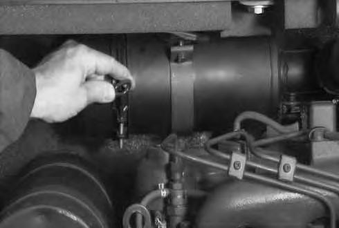
Service the air cleaner as follows:
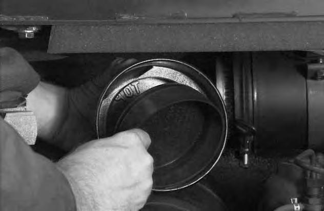
Loosen the clamp on the dust cup [C]
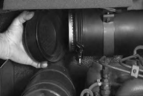
Remove the dust cup [D]
AIR CLEANER SERVICE (Cont’d)
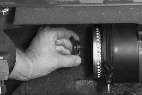
Remove the rubber cup to clean the dust cup [A]
Remove the wing nut (Item 1) [B].
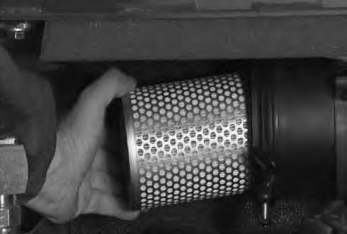
Remove the filter element [C]
Check the air cleaner housing for damage.
Wipe the canister and the seal surface clean with a clean cloth. Do Not use compressed air.
Install a new filter element. Install and tighten the wing nut.
Install the dust cup so the arrow points up.
Check that all the air cleaner hose clamps are tight.
Push the button on the condition indicator so the red ring does not show.
Fuel System
Fuel Specifications
Use Number 2 diesel fuel in the engine. During very cold temperature, Number 1 fuel can be used.
Stop and cool the engine before adding fuel. NO SMOKING! Failure to obey warnings can cause an explosion or fire.
W–2063–0887
Fuel System Service
The fuel level in the tank is indicated by the fuel gauge (Item 1) [A] when the key switch is ON.
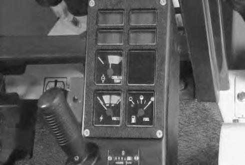
NOTE:When the fuel level reaches the 1.7 gals. (6,5 L) fuel setting, the low fuel light (Item 2) [A] will come ON to alert the operator of this condition.
Use the key to unlock the fuel fill door (Item 1) [B]
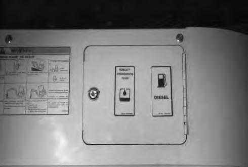
Turn the fill cap to remove it [C].
Use a clean, approved safety container to add fuel to the tank.
Add fuel only in an area that has a free movement of air and no open flames or sparks. NO SMOKING!
After the tank is full, install and tighten the fuel fill cap. Close and lock the fuel door.

Always clean up spilled fuel or oil. Keep heat, flames, sparks or lighted tobacco away from fuel and oil. Failure to use care around combustibles can cause explosion or fire which can result in injury or death.
W–2103–1285
FUEL SYSTEM (Cont’d)
Fuel System Service (Cont’d)
To remove the water and sediment from the fuel tank, turn the upperstructure until the fuel tank is centered between the rear tracks.
Open the drain valve (Item 1)[A] at the bottom of thefuel tank.
Drain all water and sediment into a container.
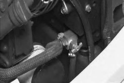
Fuel Filter
See the SERVICE SCHEDULE Page 27 for the correct service interval.
To remove water from the filter element, open the drain valve (Item 1) [B] at the bottom of the fuel filter.
Drain the water into a container. When fuel free of water emerges from the drain valve, close the drain valve.
See the SERVICE SCHEDULE Page 27 for the correct service interval of fuel filter element replacement.
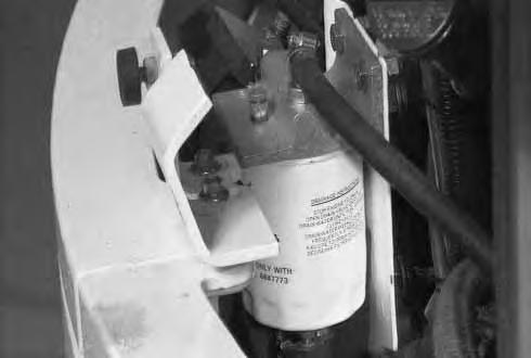
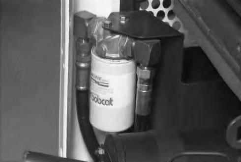
Remove the hose (Item 1) [C] from the filter housing and plug the hose, or firmly squeezethe hose, to eliminate the fuel from siphoning out of the tank when the element is removed.
Remove the fuel filter element (Item 2)[C]. Clean the area around the filter housing. Put oil on the seal of the new filter element. Install the new fuel filterelement, and hand tighten.
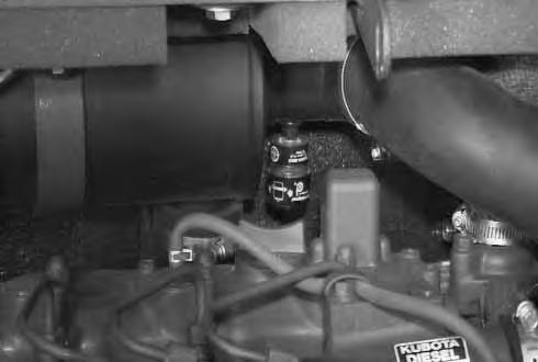
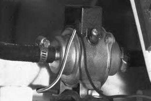
Removing Air From The Fuel System
Loosen the filter bleed screw (Item 3) [C] on the filter housing. Let the fuel gravity feed from the fuel tank until it emerges from the vent, free of air bubbles. Close the bleed screw. The fuel system has an electric fuel pump [D]. Turn the key switch to the ON position (do no start the engine). Leave the key in the ON position for a short period, or until all air is removed from the fuel system.
Engine Lubrication System
Check the engine oil every day. Stop the engine. Open the engine cover.
Remove the dipstick [A].
Keep the oil level between the marks on the dipstick. Use a good quality motor oil that meets API Service Classification of CE. (See Fuel, Coolant and Lubricants Chart, Page 52.)
Engine Oil And Filter Replacement
See the SERVICE SCHEDULE Page 27 for the correct service interval.
Use the following procedure to change the oil and filter: Run the engine until it is at operating temperature. Turn the upperstructure so the engine oil can drain between the tracks. Stop the engine.
Remove the drain plug (Item 1) [B]. Drain the oil into a container.
Remove the oil filter (Item 1) [C], using a filter wrench. Clean the filter housing surface. Put clean grease on the filter gasket. Install the new filter and hand tighten only.
Install and tighten the oil drain plug.
Remove the oil fill cap (Item 1) [D]. Put 6.3 qts. (6,0 L) of oil into the engine. (See Fuel, Coolant and Lubricants Chart & Capacity, Page 52.)
Start the engine and let it run for several minutes. Stop the engine. Check for leaks at the oil filter and the drain plug.
Check the oil level and add oil as needed to bring it to the top mark on the dipstick.
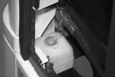
Cooling System
Coolant Level
When the engine is cool, the coolant level in the recovery tank (Item 1) [A] must be half full.
If the coolant level is low, add premixed coolant (50% water and 50% ethylene glycol) to the recovery tank.
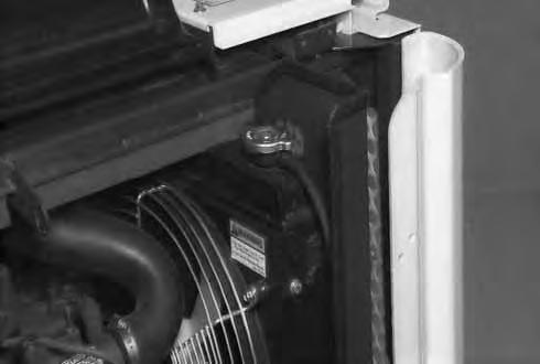
Coolant Replacement
Do not remove radiator cap when the engine is hot. You can be seriously burned.
W–2070–1285
Turn the upperstructure so there is access to the engine and radiator from between the tracks. Stop the engine.
Loosen and remove the radiator cap (Item 1) [B]
Open the radiator drain valve (Item 1) [C] at bottom of radiator.
Drain all the coolant from the system
NOTE:Also remove all coolant from the coolant recovery tank (Item 1) [A].
When all the coolant is removed, close the drain valve.
Premix coolant in a separate container.
Ethylene Glycol
Add premixed coolant; 50% water and 50% ethylene glycol to the recovery tank if the coolant level is low.
Propylene Glycol
Add premixed coolant; 43% water and 57% propylene glycol to the recovery tank if the coolant level is low.
One gallon and one pint of propylene glycol mixed with one gallon of water is the correct mixture of coolant to provide a –34°F (–37°C) freeze protection.
NOTE:Do Not mix ethylene glycol and propylene glycol in the same cooling system.
Use a refractometer to check the condition of propylene glycol in your cooling system.
Fill the radiator with the premixed coolant until it is full. Add coolant to the recovery tank until it is half full.
Run the engine at idle speed for about 5 – 10 minutes to remove the air from the cooling system (leave the radiator cap off during this operation).
Stop the engine. Check the coolant level and add as needed to bring it up to the radiator filler neck. Install the radiator cap and tighten.
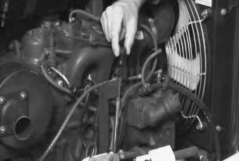
ALTERNATOR/FAN BELT ADJUSTMENT
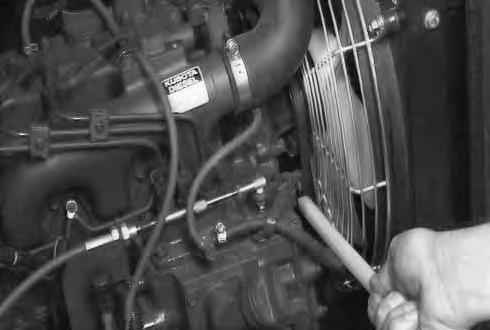
To adjust the belt tension, use the following procedure: STOP the engine. Open the engine cover.
The belt should deflect about 1/2 inch (13 mm) when pressed between the water pump pulley and crankshaft pulley with approximately 13 lbs. (58 N) pressure [A]
If the tension is not correct:
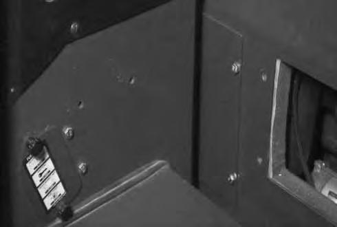
Remove the seat and the seat mount. (See Service Manual.)
Remove the four bolts and remove the access cover [B]
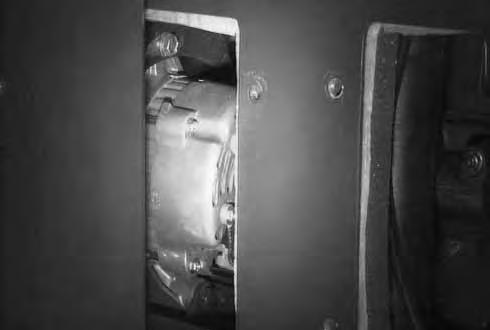
Loosen the alternator mounting bolt (Item 1) [C].
Loosen the adjustment bolt (Item 2) [C]
Move the alternator until the belt tension is correct.
Tighten the adjustment bolt and alternator mounting bolt. Replace the belt if it has stretched or there are cracks in the belt. Check the pulley grooves, make sure the belt is not in contact with the bottom of the grooves in the pulleys.
Electrical System
The excavator has a 12 volt, negative ground electrical system.
Fuses
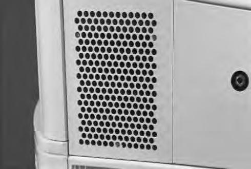
The fuses are located in the lower part of the right hand control console [A]
Loosen the two knobs (Item 1)[A] and remove the access plate.
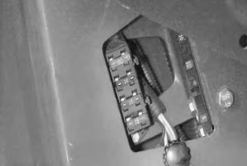
1. FUSE – 20 Amp: This fuse supplies powerto the key switch [B].
2. FUSE – 10 Amp: This fuse supplies power to the dash panel and the hourmeter [B].
3. FUSE – 15 Amp: This fuse supplies power to the light switch [B]
4. FUSE – 15 Amp: This fuse supplies power to the horn and the heater (if equipped).
Replace the fuses with the same type and capacity.
NOTE:Before replacing any fuse, find and fix the problem that caused the fuse to blow. Make sure the key switch is in the OFF position before replacing the fuse.
Service The Electrical System
Remove the three bolts and remove the right side cover [C]
NOTE:On later model excavators, the start key is used to unlock the cover.
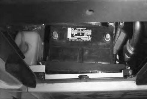
The battery cables must be clean and tight. Remove any acid or corrosion from the battery and cables using a sodium bicarbonate and water solution. Cover the battery terminals and cable ends with battery saver grease [D] Check for broken or loose connections.
If the battery cables are removed for any reason, disconnect the negative (–) cable first and when installing the battery cables, make the last connection the negative (–) cable to the battery.
With factory equipped battery, no maintenance is needed as this is a maintenance free battery.
If the machine has a Melroe parts replacement battery installed, check the electrolyte level in the battery. (See Battery Manual P/N 6566047 for additional information.) If it is lower than 1/2 inch (13 mm) above the plates, add distilled water only.
Batteries contain acid which burns eyes and skin on contact. Wear goggles, protective clothing and rubber gloves to keep acid off body.
In case of acid contact, wash immediately with water. In case of eye contact get prompt medical attention and wash eye with clean, cool water for at least 15 minutes.
If electrolyte is taken internally drink large quantities of water or milk! DO NOT induce vomiting. Get prompt medical attention.
ELECTRICAL SYSTEM (Cont’d)
Using A Booster Battery (Jump Starting)
If jump starting the excavator from a second machine:
When jump starting the excavator from a battery installed in a second machine. Make sure that the second machine is NOT running while using the glow plugs. High voltage spikes from a running machine can burn out the glow plugs.
I–2060–0195
If it is necessary to use an extra battery to start theengine. BE CAREFUL!
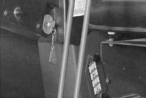
Make sure the swing locking lever is in the engaged position.
The key switch must be in the OFF position.
The booster battery must be 12 volt.
Remove the three bolts (Item 1) [A] and remove the right side cover.
NOTE:On later model excavators, the start key is used to unlock the cover.
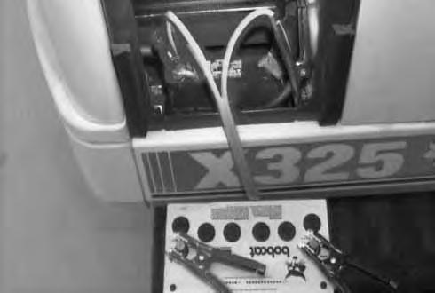
Connect the end of the first cable to the positive (+) terminal of the booster battery. Connect the other end of the same cable to the positive (+) terminal (Item 1) [B] & [C] of the machine battery.
Connect the end of the second cable to the negative (–) terminal of the booster battery. Connect the other end of the same cable to the frame (Item 2) [B].
NOTE:Also see Cold Temperature Starting Condition Page 15.
Start the engine. After the engine is running, remove the cable (Item 2) [B] connected to the frame first. Disconnect the cable from the machine battery (Item 1) [B].
Damage to the alternator can occur if:
• Engine is operated with battery cables disconnected.
• Battery cables are connected when using a fast charger or when welding on the excavator. (Remove both cables from the battery.)
• Extra battery cables (booster cables) are connected wrong.
I–2023–1285
Keep arcs, sparks, flames and lighted tobacco away from batteries. When jumping from booster battery make final connection (negative) at engine frame.
Do not jump start or charge a frozen or damaged battery. Warm battery to 60°F. (16°C.) before connecting to a charger. Unplug charger before connecting or disconnecting cables to battery. Never lean over battery while boosting, testing or charging.
Battery gas can explode and cause serious injury.
ELECTRICAL SYSTEM (Cont’d)
Removal and Installation of the Battery (S/N 511820001–511820294)
Remove the three bolts and remove the right side cover [A]
Disconnect the negative (–) cable (Item 1) [B] first. Disconnect the positive (+) cable (Item 2) [B]
Remove the two wing nuts (Item 1) [C] and remove the holddown clamp (Item 2) [C].
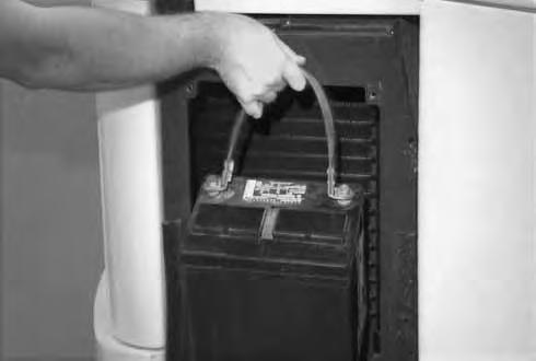
Remove the battery from the compartment [D]
Always clean the terminals and cable ends, even when installing a new battery.
Install the battery. Install the holddown clamp and tighten the bolt.
Connect the battery cables. Connect the negative (–) cable (Item 1) [B] last to prevent sparks at the terminal.
Batteries contain acid which burns eyes and skin on contact. Wear goggles, protective clothing and rubber gloves to keep acid off body.
In case of acid contact, wash immediately with water. In case of eye contact get prompt medical attention and wash eye with clean, cool water for at least 15 minutes.
If electrolyte is taken internally drink large quantities of water or milk! DO NOT induce vomiting. Get prompt medical attention.
W–2065–1296
ELECTRICAL SYSTEM (Cont’d)
Removal and Installation of the Battery (S/N 511820295 & Above)
Remove the three bolts and remove the right side cover [A].
NOTE:On later model excavators, the ignition key is used to unlock the cover.
Disconnect the negative (–) cable (Item 1) [B] first. Disconnect the positive (+) cable (Item 2) [B]
Remove the two wing nuts (Item 1) [C] and remove the holddown clamp (Item 2) [C]
Remove the battery from the compartment [D]. Always clean the terminals and cable ends, even when installing a new battery.
Install the battery. Install the holddown clamp and tighten the bolt.
Connect the battery cables. Connect the negative (–) cable (Item 1) [B] last to prevent sparks at the terminal.
Batteries contain acid which burns eyes and skin on contact. Wear goggles, protective clothing and rubber gloves to keep acid off body.
In case of acid contact, wash immediately with water. In case of eye contact get prompt medical attention and wash eye with clean, cool water for at least 15 minutes.
If electrolyte is taken internally drink large quantities of water or milk! DO NOT induce vomiting. Get prompt medical attention.
W–2065–1296
HYDRAULIC SYSTEM Checking and Adding Fluid
To check and add hydraulic fluid to the reservoir, use the following procedure:
Put the machine on a flat level surface.
Retract the arm and bucket cylinders, put the bucket on the ground and raise the blade. Stop the engine.
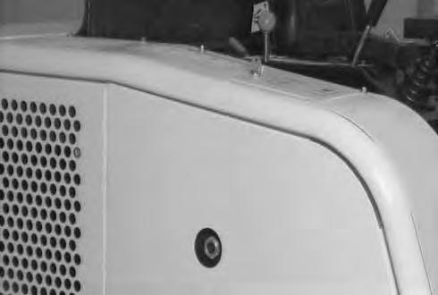
Check the hydraulic fluid level, it must be visible in the sight gauge (Item 1) [A] located on the side of the hydraulic reservoir.
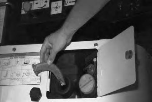
If the fluid level is not correct, open the hydraulic tank access door [B].
Remove oil fill cap [B]
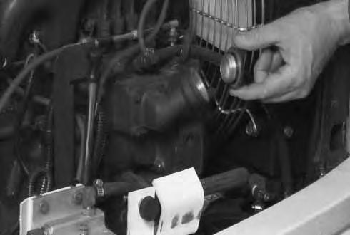
Check the condition of the fill strainer [C]. The screen must be installed in fill neck when adding oil.
Add the correct fluid to the reservoir untilit is visible in the sight gauge. (See Fuel, Coolant and Lubricants Chart, Page 52.)
Install the reservoir cap and close and lock the access door.
Replacement of the Hydraulic Filter
See the SERVICE SCHEDULE Page 27 for the correct service interval.
Open the engine cover.
Use a filter wrench and remove the filter element (Item 1) [D].
Clean the housing where the filter gasket makes contact.
Put clean hydraulic fluid on the gasket. Install the new filter element and hand tighten only.
Start the engine. Run the machine through the hydraulic functions. Stop the engine. Check the fluid level at the reservoir and add as needed. Check around the filter for leaks.
HYDRAULIC SYSTEM (Cont’d)
Hydraulic Reservoir
See the SERVICE SCHEDULE Page 27 for the correct service interval.
Move the upperstructure so there is clearance for the reservoir drain between the tracks.
Retract the arm and bucket cylinders, lower the bucketto the ground. Stop the engine.
Remove the hydraulic filter. (See Page 39.)
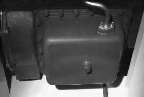
Remove the drain plug from the bottom of the reservoir [A].
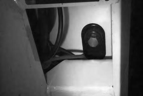
Drain the fluid into a container.
Install the drain plug.
Add approximately 6.9 gals. (26 L) of fluid to the reservoir. (See Fuel, Coolant and Lubricants Chart Page 52.)
Run the machine through the hydraulic functions. Check the fluid level and add as needed.
Always clean up spilled fuel or oil, Keep heat, flames, sparks or lighted tobacco away from fuel and oil. Failure to use care around combustibles can cause explosion or fire which can result in injury or death.
W–2103–1285
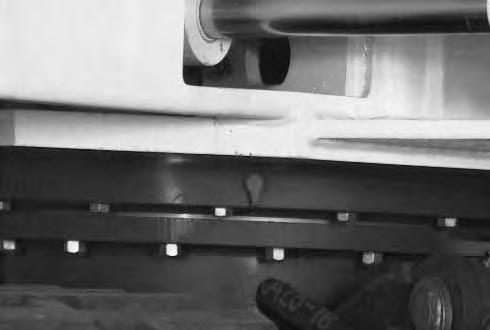
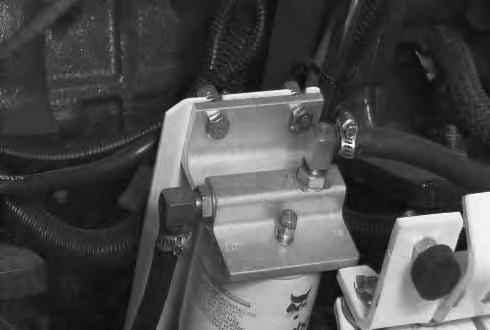
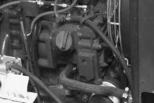
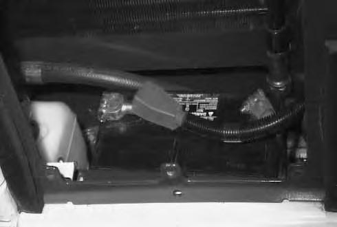
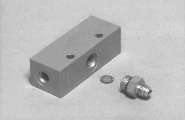
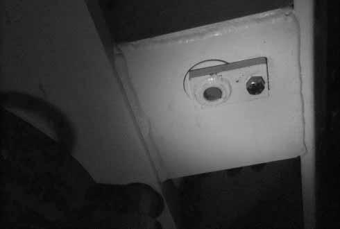
Case Drain Line Filter
NOTE:Case drain block removed for photo clarity.
Remove the hose from the bottom fitting (Item 1) [B]
Remove the fitting (Item 1) [B]
With a finger tip, dislodge the screen (Item 2)[B] from the inside of the drain block.
Clean the screen with solvent and reinstall.
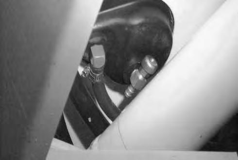
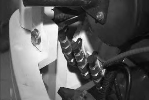
Diagnostic Couplers
The diagnostic couplers are located on each hydraulic pump (Item 1) [C]
The couplers can be used to check circuit pressures. (Refer to the Service Manual.)
Lubrication Of The Hydraulic Excavator
Lubricate the Hydraulic Excavator as specified in the SERVICE SCHEDULE Page 27 for the bestperformance of the machine.
Always use a good quality lithium based multi–purpose grease when lubricating the machine. Apply the lubricant until extra grease shows.
Ref.Description (# of Fittings)
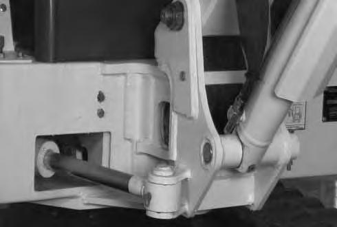
1.Blade Cylinder Rod End, every 8–10 hours (1) [A]
2.Blade Pivots, every 8–10 hours (2) [A].
3.Blade Cylinder Base End, every 8–10hours (1) [A].
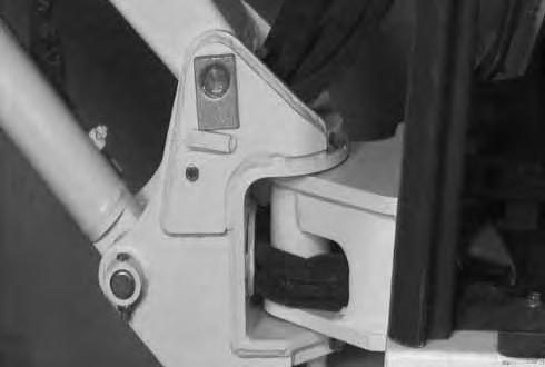
4.Boom Swing Bracket Pivot, every 8–10 hours (2) [B]

5.Boom Base Pivot, every 8–10 hours (1) [B].
6.Boom Cylinder Base End, every 8–10 hours (1)[C].
7.Boom Swing Cylinder Rod End, every 8–10 hours (1) [C].
8.Swing Circle Pinion, every 50 hours (1) [C] Install four pumps of grease from a grease gun into the grease fitting. Rotate the upperstructure 180° and install four more pumps of grease into the grease fitting.
9.Boom Cylinder Rod End, every 8–10 hours (1) [D].
8–10 hours (1) [D]
LUBRICATION OF THE HYDRAULIC EXCAVATOR (Cont’d)
Ref. Description (# of Fittings)
11.Arm Cylinder Rod End , every 8–10 hours (1) [A]
12.Arm Base Pivot, every 8–10 hours (1) [A].
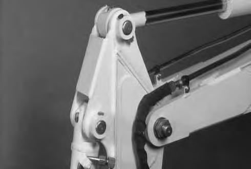
13.Bucket Cylinder Base End, every 8–10 hours (1) [A]
14.Bucket Cylinder Rod End, every 8–10 hours (1)[B]
15.Bucket Link Pivots, every 8–10 hours (2) [B]
16.Bucket Pivots, every 8–10 hours (4) [B].
17.Swing Circle Ball Bearings, every 50 hours (2) [C]
NOTE:Do not over–grease the swing circle or damage to the seals could result. Install four to five pumps of grease from a grease gun into each of the two grease fittings. Rotate the upper structure 90° and install four to five pumps of grease into each of the two grease fittings.
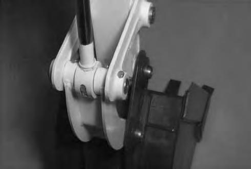
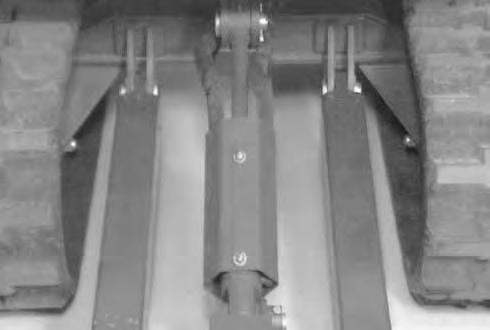
18.Boom Swing Cylinder Base End, every 8–10 hours (1) [D].
(Under the right side of the upperstructure)