14 minute read
SAFETY INSTRUCTIONS


SAFETY IS THE OPERATOR’S RESPONSIBILITY
The Bobcat Hydraulic Excavator is a maneuverable, compact machine. In operation, itis rugged and useful under a wide variety of conditions. This presents an operator with hazards associated with off highway, rough terrain applications. The Hydraulic Excavator has an internal combustion engine with resultant heat and exhaust. All exhaust gases can kill or cause illness so the Bobcat Hydraulic Excavator must be run with adequate ventilation.
The dealer explains the capabilities and restrictions of the excavator and attachments for each application. The dealer demonstrates the safe operation of the excavator according to Melroe’s instructional materials; which are also available to all operators. The dealer can also identify unsafe modifications or use of unapproved attachments. The attachments are designed for rated capacity and secure fastening to the Bobcat Hydraulic Excavator. The user must check with the dealer or Melroe Company literature or load diagram to identify safe loads.
The following publications provide information on the safe use of the excavator and attachments:
• The Delivery Report is used to check whether complete instructions have been given to the new owner, and that the machine is in safe operating condition.
• The Operation & Maintenance Manual delivered with each Bobcat Hydraulic Excavator gives operating information as well as routine maintenance information. It is part of the machine and must stay with the machine when it is sold. Replacement Operation & Maintenance Manuals can be purchased from your dealer.
• Every Bobcat Hydraulic Excavator has machine signs (or decals) which instruct on the safe operation and care. The signs and their location are shown in the Operation & Maintenance Manual. Replacement signs are available from your Bobcat Hydraulic Excavator dealer.
• The Bobcat Hydraulic Excavator has a plastic Operator’s Handbook fastened to the operator cab. It’s instructions are convenient to the operator. The handbook is available from your dealer in an English edition or one of the following languages: French, German, Italian, Dutch, Spanish, Portuguese, Finnish, Danish & Spanish.
• The CIMA safety manual contains information for safe operation and maintenance.
• The Service and Parts Manuals are available from your Bobcat Hydraulic Excavator dealer for use by mechanics todo shop–type service and repair work.
• The dealer and owner/operator review the recommended uses of the excavator and attachments at the time of delivery of the excavator. If change of the use of the excavator occurs, the owner/operator must ask the dealer for recommendations on the new use of the excavator.
Before Operating The Bobcat Hydraulic Excavator
Safety Alert Symbol: This Safety Symbol is used for important safety messages. When you see this symbol, follow safety message to avoid personal injury or death.
Operator must have instructions before running the machine. Untrained operators can cause injury or death.
The Hydraulic Excavator must be in good operating condition before use. Check all of the items on the Service Schedule under the 8 – 10 hour column.
Warnings on the machine in the manuals are for your safety. Failure to obey warnings can cause injury or death.
This notice identifies procedures which must be followed to avoid damage to the machine.
SAFE OPERATION NEEDS A QUALIFIED OPERATOR*
A QUALIFIED OPERATOR MUST DO THE FOLLOWING:
• UNDERSTAND THE WRITTEN INSTRUCTIONS, RULES AND REGULATIONS
• The written instructions from Melroe Company include the delivery report, operator handbook, Operation & Maintenance Manual, CIMA manual and machine signs (decals).
• Check the rules and regulations at your location.
• HAVE TRAINING WITH ACTUAL OPERATION
• Operator training must consist of a demonstration and verbal instruction. This training is given by your excavator dealer before the excavator is delivered.
• The new operator must start in an area without bystanders and use all the controls until he can operate the excavator safely under all conditions of the work area.
• KNOW THE WORK CONDITIONS
• For each material to be handled, the operator must know how to avoid exceeding the rated lift capacity of the excavator. For example, you should not use the excavator for lifting heavy objects.
• The operator must know any prohibited uses or work areas, for example, he needs to know about excessive slopes.
• Know the location of any underground lines. Call local utilities or ONE CALL before you dig.
• Wear tight fitting clothing. Always wear safety glasses when maintaining or servicing excavator. Safety glasses, hearing protection or an excavator special application kit are required for some work. See your dealer about Melroe Safety equipment.
* For an operator to be qualified, he must not use drugs or alcoholic drinks which impair his alertness or coordination while working. An operator who is taking prescription drugs must get medical advice to determine if he can safely operate a machine.
Fire Prevention
The excavator has several components that are at high temperature under normal operating conditions. The primary source of high temperatures is the engine and exhaust system. The electrical system, if damaged or incorrectly maintained, can be a source of arcs or sparks. These conditions make it important to avoid applications where explosive dust or gases can be ignited by arcs, sparks or heat.
Flammable debris (leaves, straw, etc.) must be removed regularly. If flammable debris is allowed to accumulate, it will increase the fire hazard. The excavator must be cleaned as often as necessary to avoid this accumulation. This flammable debris in the engine compartment can be a fire hazard when the machine is parked with a hot engine.
The spark arrestor muffler is designed to control the emission of hot particles from the engine and exhaust system, but the muffler and the exhaust gases are still hot. This spark arrestor muffler does not change the need to avoid use of the excavator in an atmosphere with explosive dust or gases or where the exhaust can contact flammable material.
• Do not use the Hydraulic Excavator where explosive dust or gases can be ignited by arcs, sparks, hot components or exhaust gases.
• The engine compartment and engine cooling system must be inspected every day and cleaned if necessary to prevent overheating. Remove all flammable material.
• Check all electrical wiring and connections for damage. Keep the battery terminals clean and tight. Repair or replace any damaged part.
• Check fuel and hydraulic tubes, hoses and fittings for damage and leakage. Tighten or replace any parts that show leakage. Always clean fluid spills.
• Do not use ether or starting fluids on any engine which has glow plugs. These starting aids can explode and injure bystanders.
• Always clean the excavator before doing any welding. Cover rubber hoses, battery and all other flammable parts. Keep a fire extinguisher near the machine when welding.
• Stop the engine and let it cool before adding fuel. No smoking!
• Use the procedure in Operation & Maintenance Manual for jump starting the battery.
MACHINE SIGNS (DECALS)
Follow the instructions on all the Machine Signs (Decals) thatare on the excavator. Replace any damaged machine signs and be sure they are in the correct locations. Replacementmachine signs are available from your Bobcat Excavator dealer.
325 (S/N 511820001–511821999) Excavator
MACHINE SIGNS (DECALS) (Cont’d)
Follow the instructions on all the Safety Signs (Decals) that are on the excavator. Replace any damaged safety signs and be sure they are in the correct locations. Safety signs are available from your Bobcat Excavator dealer.
325 (S/N 511820001–511821999)
Getting On And Off The Machine
Use the grab handles, the tracks and the safety tread to get on and off the machine [A]

Fasten the seat belt snugly. Adjust the seat belt so that the buckle is centered between the hips [B]

Lower starting the
Seat
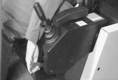
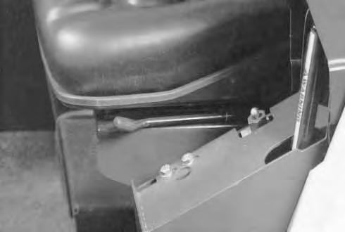
The operator seat can be adjusted as follows:
Use the lever (Item 1)[A] to slide the seatback or forward for easy reach of the machine controls.
NOTE:For ease of access to the seat adjusting lever, have the left hand console in the raised position.
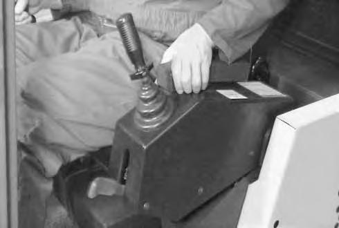
The handle (Item 1) [B] has three adjustments for operator weight. Rotate the handle to change the adjustment.
Turn the knob (Item 2) [B] to angle the back of the seat for operator comfort.
Control Console Lever Lock
The control lock (Item 1) [C] disconnects the hydraulics from the joystick control levers when the left control console is in the raised position. (The joystick control levers will not operate with the console raised).
NOTE:The travel levers, blade lever, boom swing pedal and the attachment operation pedal functions are NOT affected by the control lock.

CONTROL CONSOLE LEVER LOCK (Cont’d)
Lower the control console to engage the joystick control levers [A]
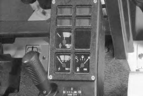
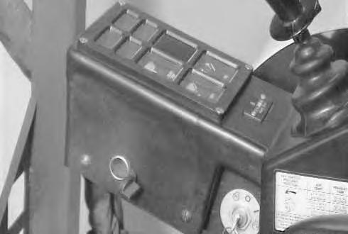
Instrument Panel
The instrument panel has the following instruments [B]:
1. PREHEAT INDICATOR LAMP – When turning the key switch to the HEAT position, the light comes ON, showing the glow plugs are heating.
2. ENGINE TEMPERATURE LAMP – Overheat indicator, when the engine coolant temperature exceeds the allowable temperature range, the light comes ON and the audible alarm sounds. STOP the engine.
3. LOW FUEL INDICATOR LAMP – When fuel level is low (1.7 gal. & [6,5 L]), the light comes ON. Add fuel.
4. FUEL GAUGE – Shows the amount of fuel in the tank.
5. HOURMETER – Records total operating hours. (If the key switch is left in the run position, with the engine OFF, the hourmeter will continue to run and the audible alarm will sound.)
6. CHARGING GAUGE – Shows battery charge rate.
7. ENGINE TEMPERATURE GAUGE – Shows engine coolant temperature. Audible alarm sounds when temperature reaches 230°F (110°C).
8. ENGINE OIL LAMP – When the engine oil pressure is low, the light comes ON and audible alarm sounds. STOP the engine.
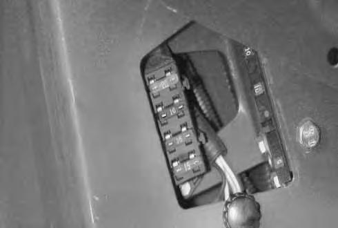
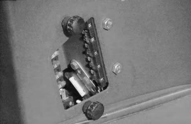
Fuses
The fuses are located in the right hand control console, below the seat [C]

Loosen the two knobs (Item 1)[C] and remove the access plate.
1. FUSE – 20 Amp: This fuse supplies powerto the key switch [D]
2. FUSE – 10 Amp: This fuse supplies power to the dash panel, the hourmeter and the fuel pump [D]
3. FUSE – 15 Amp: This fuse supplies power to the light switch [D].
4. FUSE – 15 Amp: This fuse supplies power to the horn and the heater (if equipped) [D]
Audible Alarm
An audible alarm (Item 1) [A] located in the right hand console, will sound when these conditions exists:
When the key is in the ON position with the engine OFF.
When low engine oil pressure exists.
When high engine coolant temperature exists.
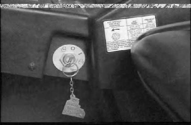
KEY SWITCH
The key switch has the following functions [B]:
A.Key switch is OFF & the engine stops.
B.PREHEAT position, hold switch in this position to activate the glow plugs for starting in cold weather conditions. (See Decal (Item 1)[B] for glow plug heating times or Page 15).
C.START the engine.
D.ON (run) position, once the engine is running, release the key and this position is obtained automatically.
NOTE:Always turn key switch and all accessories to OFF position after the engine is stopped or battery will discharge. Audible alarm will sound if the key is in the ON position with the engine stopped.
See Pages 14 and 15 for the startingprocedure and Page 11 for the stopping the engine.
LIGHT SWITCH
The light switch (Item 1) [C] has the following functions:
A.Light switch is OFF.
B.Strobe light/flasher (if equipped).

C.Front work lights and the fuel gauge back light (plus any lights used with position B).
D.Additional work lights (if equipped) – (plus any lights used with positions B and C).
Auxiliary Power Outlet
The auxiliary power outlet (Item 1) [D] is used for supplying electrical current for operator supplied electrical options. This outlet has 12 electrical current at all times.
CAB ELECTRICAL (Cab Option)
The cab overhead console has the following components [A]:
1. FUSE – (5 Amp) Cab, this fuse (Item 1)[A] supplies the power for the wiper/washer and for the interior light.
2. WIPER/WASHER SWITCH – Turn the switch (Item 2) [A] to activate wipers, OFF–LOW–HIGH. Push the switch IN to activate the washer.
3. INTERIOR LIGHT – Push the button (Item 3)[A] on the side of the light to activate.
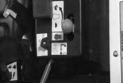
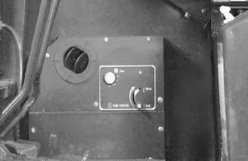
Heater Control
The heater has the following controls [B]:
1. FAN SWITCH – Turn the switch (Item 1) [B] to activate fan, OFF–LOW–MED–HI.
2. TEMPERATURE CONTROL – Move the lever (Item 2) [B] up to increase the temperature – move the lever down to decrease the temperature.
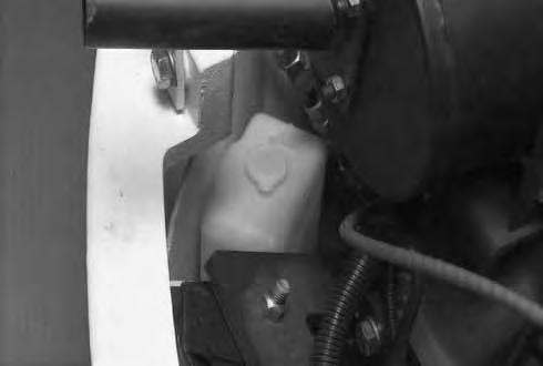
Washer
Open the engine cover. The washer tank is located in the left rear corner of the engine compartment.
Remove the window washer tank cap (Item 1)[C] and fill with washer fluid. (The Wiper/Washer switch (Item 2) [A] is used to activate the washer pump.).

Control Levers
The work equipment is operated by using the left and right control levers (joysticks) [A] & [B]
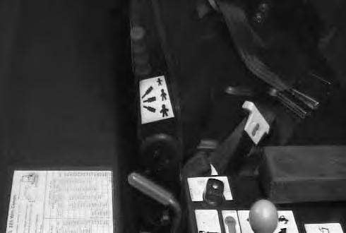
Operation Of Left Control Lever (ISO)
Arm and Swing (Decal P/N 6589741)
The left lever is used to operate the arm and swing the upperstructure [A]:
1.Arm Out
2.Arm Out and Swing Right
3.Swing Right
4.Arm In and Swing Right
5.Arm In
6.Arm In and Swing Left
7.Swing Left
8.Arm Out and Swing Left
Before swinging the upperstructure, make sure the swing lock is disengaged.
Operation Of Right Control Lever (ISO)
Boom and Bucket (Decal P/N 6589740)
The right lever is used to operate the boom and bucket [B]:
1.Boom Lower
2.Boom Lower and Bucket Dump
3.Bucket Dump
4.Boom Raise and Bucket Dump
5.Boom Raise
6.Boom Raise and Bucket Curl
7.Bucket Curl
8.Boom Lower and Bucket Curl
AVOID INJURY OR DEATH
Before leaving the machine:
• Lower the work equipment to the ground.
• Lower the blade to the ground.
• Stop the engine & remove the key.
CONTROL LEVERS (Cont’d)
The work equipment is operated by using the right and left control levers (joysticks) [A] & [B]
Operation Of Left Control Lever (STANDARD)
Boom and Swing (Decal P/N 6589842)
The left lever is used to operate the boom and swing the upperstructure [A]:
1.Boom Lower
2.Boom Lower and Swing Right
3.Swing Right
4.Boom Raise and Swing Right
5.Boom Raise
6.Boom Raise and Swing Left
7.Swing Left
8.Boom Lower and Swing Left
Before swinging the upperstructure, make sure the swing lock is disengaged.
Operation Of Right Control Lever (STANDARD)
Arm and Bucket (Decal P/N 6589843)
The right lever is used to operate the armand bucket [B]:
1.Arm out
2.Arm Out and Bucket Dump
3.Bucket Dump
4.Arm In and Bucket Dump
5.Arm In
6.Arm In and Bucket Curl
7.Bucket Curl
8.Arm Out and Bucket Curl
AVOID INJURY OR DEATH
Before leaving the machine:
• Lower the work equipment to the ground.
• Lower the blade to the ground.
• Stop the engine & remove the key.
W–2196–0595
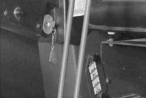
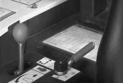
Swing Locking Lever
When the swing locking lever (Item 1) [A] is engaged (locked position), the upperstructure of the excavator is locked to the track frame and will not swing.
Avoid Injury
The swing lock lever must be engaged when transporting the machine.
Horn Button
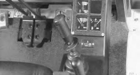
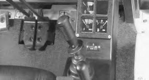
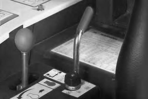
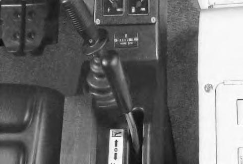
Speed Control Lever
The speed control lever is used to control the engine speed [A]:
1.LOW IDLE POSITION – Pull the lever backward (position 1) for low idle, (approximately 1000 RPM).
2.HIGH IDLE POSITION – Push the lever fully forward (position 2) for full engine RPM, (approximately 2500 RPM).
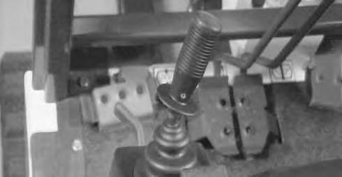
Engine Stop Control
The speed control lever also controls stopping theengine. Push the speed control lever fully towards the rear of the machine and hold in this position until the engine comes to a complete stop [B]
Release the lever and it will return to the low idleposition. Turn the ignition switch to the OFF position.
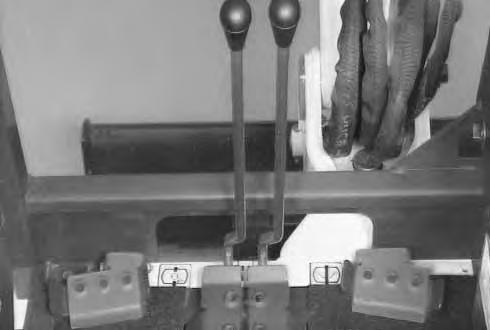
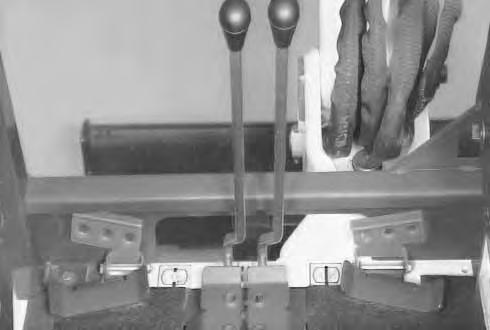
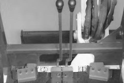
STEERING LEVERS/FOOT PEDALS Forward and Reverse Travel
Slowly push or pull the right (Item 1) [A] and left (Item 2) [A] steering levers/foot pedals for forward or reverse travel.
• Check the blade location before traveling. When the blade is to the rear, operate the steering levers/foot pedals in the opposite direction to when the blade is in the front.
• Move the steering levers/foot pedals slowly. Abrupt lever motion will cause the machine to jerk.
Turning
Operate the steering levers/foot pedals in the following manner to change the direction of a stationary machine (with blade forward):
LEFT TURN – Push the right steering lever/foot pedal forward to turn to the left in the forwarddirection [B]. Pull it back to make the machine turn left in the reverse direction [C]
RIGHT TURN – Push the left steering lever/foot pedal forward to turn to the right in the forward direction[B]. Pull it back to make the machine turn to the right in the reverse direction [C]
Changing direction of a moving machine, the left and right steering levers/foot pedals are pushed or pulled in the same direction.
Making A Counter–Rotation Turn
To counter–rotate the machine to the left, pull the left steering lever/foot pedal back and push the right steering lever/foot pedal forward [D]
To counter–rotate the machine to the right, push left steering lever/foot pedal forward and pull the right steering lever/foot pedal back [D].
Boom Swing Pedal
Raise the pedal lock/footrest (Item 1) [A] to operate the boom swing pedal.
Push the pedal (Item 2) [A] on the right side to swing the boom to the right and push the pedal on the left side to swing the boom to the left.
NOTE:The purpose of the boom swing pedal is to offset the boom with respect to the upperstructure.
AUXILIARY OPERATION PEDAL LOCK/FOOTREST
Raise the pedal lock/footrest (Item 3) [A] to operate the attachment operation pedal.
The pedal (Item 4) [A] controls optional equipment when mounted on the arm.
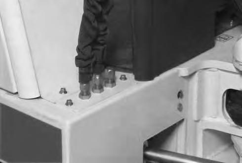
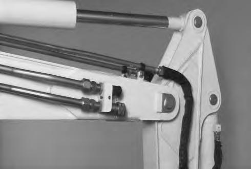
The excavator is equipped with 2–way flow auxiliary lines. Push the pedal (Item 4) [A] to activate the hydraulic function. The right side of the pedal is hydraulic pressure/flow to the female coupler and the left is hydraulic pressure/flow to the male coupler [A] and [C]
To change to one–way flow (return to tank with low back pressure) move the center hose (Item 1) [B] to the fitting (Item 2) [B] and cap the center fitting. The pedal willnow supply fluid when pushed to the right side only.
Install the center hose (Item 1) [B] onto the fitting (Item 2) [B] when using the hydraulic breaker.
The female coupler (Item 1) [C] is pressure, the male coupler (Item 2) [C] is return when pedal is pushed to the right.
Instructions are necessary before operating or servicing machine. Read Operation & Maintenance Manual, Handbook and signs (decals) on machine. Follow warnings and instructions in the manuals when making repairs, adjustments or servicing. Check for correct function after adjustments, repairs or service. Failure to follow instructions can cause injury or death.
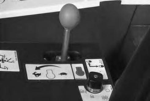
Blade Control Lever
The lever (Item 1)[D] is used to raise and lower the blade:
Position A – Pushed Forward – Lowers the blade.
Position B – Neutral – Blade is stopped and held in position.
Position C – Pulled Back – Raises the blade.
NOTE:Keep the blade lowered when digging to stabilize machine.
Daily Inspection
Check the following items before starting each day of operation:
• Operator Canopy or Cab (ROPS) and mounting hardware.
• Seat belt and its mounting hardware.
• Damaged decals, replace as needed.
• Air cleaner and intake hoses.
• Engine coolant level and for coolant leaks.
• Engine oil level and for engine leaks.
• Clean engine area of any flammable material.
• Hydraulic fluid level and system for leaks.
• Grease all pivot points.
• Cylinder and attachment pivot points.
• Track tension.
• Repair broken and loose parts.
Instructions are necessary before operating or servicing machine. Read Operation & Maintenance Manual, and signs (decals) on machine. Follow warnings and instructions in the manuals when making repairs, adjustments or servicing. Check for correct function after adjustments. repairs or service. Failure to follow instructions can cause injury or death.
W–2144–0189
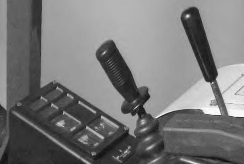
STARTING/STOPPING THE ENGINE
Normal Starting Procedure (With Engine Warm)
Fasten the seat belt.
Lower the left control console to the locked position.
Put all control levers in the neutral position [A]
Pull the engine speed control leverto the low idle position (Item 2) [B]
Move the key to HEAT position (if required), the light will come on. Hold the key in the heat position for 5 to 10 seconds [C]
Turn the key to the START position [D]
When the engine is started, release the key and it will return to the run (ON) position.
Stop the engine if the warning lights and the audible alarm do not go OFF. Check for the trouble before starting the engine again.
Do not engage the starter for longer than 15 seconds at a time. Longer use can damage the starter by overheating. Cool the starter for one minute between uses.
I–2034–0284


