CONTROL FUNCTIONS (CONT’D) Application Interface Outline (Cont’d) •
Constant speed mode
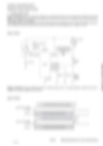
[Figure 10-40-31] shows the connection diagram for constant speed mode. Do not connect the indicator lamp power supply to the IGNSW (E7) terminal.Turning current from the APP-IP terminal to the IGNSW terminal may cause the EECU power supply to not shutdown. The indicator lamp can be connected to the APP-OP2 (E2) terminal optionally, but in this case the coolant temperature alarm indication and block heater control cannot be done [See "Terminal assignment" on page 10-40-51].
Figure 10-40-31
Sub relay Main Relay BR R
C B
Do not connect the indicator lamp power supply to IGNSW terminal
VB(E48)
Key SW MAIN-RLY(E34)
IGNSW(E7)
Batt.12V
ECU
Indicator lamp
APP-IP6(E6) APP-IP4(E17) APP-IP3(E9)
Speed 1
Speed 2
E45,E47
Speed selection enable
[Figure 10-40-32] shows the operation timing for constant speed mode. The speed selection enable switch (E6) is available in two types: toggle and momentary.
Figure 10-40-32
0: Constant speed mode (lock switch) Speed selection enable APP-IP6 Operation
Via input terminals APP-IP3/APP-IP4
1: Constant speed mode (one-touch switch) Speed selection enable APP-IP6 Operation
Via input terminals APP-IP3/APP-IP4
10-40-31 79 of 182
E55W, E60, E80 Electronic Control System Manual

