CONTROL FUNCTIONS (CONT’D) Application Interface Outline (Cont’d)
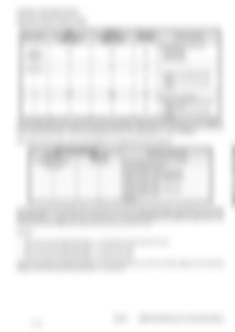
Map setting
Main Accelerator sensor APS (E35)
Reserve Accelerator sensor REAN (E37)
CAN input (E39, E40)
0 (Generator standard)
Œ
Œ
Œ
1 (Standard)
Å
Œ
Œ
2
Å
Å
Œ
3 4
Œ Å
Œ Œ
Å Å
6
Å
Å
Œ
Priority operation By the following contact input • APP-IP6 (E6) • APP-IP3 (E9) • APP-IP4 (E17) • Priority in the high-speed side sensor • Priority in the normal operation sensor Priority in the CAN input • Priority in the lastly used sensor (initially main) • Priority in the normal operation sensor
The accelerator position sensor input (APS: E35) and the backup analog sensor input (REAN: E37) can be flagged so that the corresponding sensor types are changed (see table below). These inputs have been flagged so that accelerator sensor signals (flag setting: 1) and foot pedal signals per SAE J1843 (flag setting: 2 - 4) can be applied. When these inputs are open, they must be flagged to 0 to disable sensor failure detection. ECU terminal setting flag APS: E35 REAN: E37 0(Generator standard) 0(Standard) 1(Standard) 1 2
2
3
3
4
4
-
5
Connection sensor type No connection (failure detection disabled) Normal accelerator sensor Foot pedal (SAE J1843 configuration) Analog + APP-IP2: NO & APP-IP7:NC) Foot pedal (SAE J1843 configuration) Analog + APP-IP2: NO Foot pedal (SAE J1843 configuration) Analog + APP-IP7: NC (reserve)
To connect the accelerator position sensor input (APS: E35) and the backup analog sensor input (REAN: E7) to the foot pedal (flag setting: 2 - 4), APP-IP2: E14 and APP-IP7: E13 must be configured to enable reception of signals from the foot pedal switch. In addition, APP-IP2: E14 and APP-IP7: E13 must be configured to enable connection with an NO switch and NC switch respectively. Åi(Set APP-IP2 to NO and APP-IP7 to NC. Example: •
When ECU terminal setting flag setting = 2, set APP-IP2 to NO and APP-IP7 to NC.
•
When ECU terminal setting flag setting = 3, set APP-IP2 to NO.
•
When ECU terminal setting flag setting = 4, set APP-IP7 to NC.
When the foot pedal connection is selected, it’s recommended that you set the low idling voltage and the high idling voltage of ASP terminal and REAN terminal to 1.0 V and 3.5 V.
10-40-23 71 of 182
E55W, E60, E80 Electronic Control System Manual

