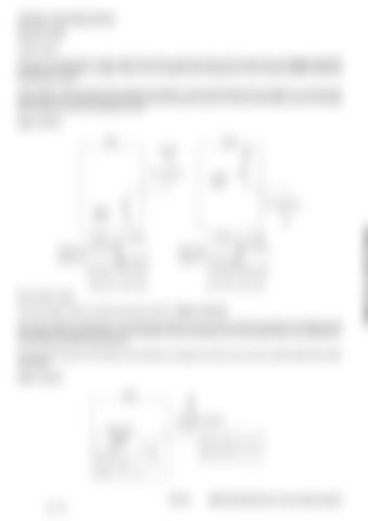
CONTROL FUNCTIONS (CONT’D) General (Cont’d) Contact output There are two schemes for contact output of the E-ECU: high-side output and low-side output. See [Figure 10-40-11] and [See "I/O description" on page 10-20-11] for the details of the Eco-governor E-ECU contact output’s sink/source and allowable current. In this manual, output transistor ON is referred to as logical "1" and output transistor OFF as logical "0". In the high-side output scheme, the output terminal goes high when the transistor turns off. In the low-side output scheme, the output terminal goes low when the transistor turns off. Figure 10-40-11
ECU
ECU Batt.12V
Sink
VB
Load
Contact output
Source
Load
Contact output
Tr=OFF
Tr=ON
Voltage=High
Voltage=High
Voltage=Low
Voltage=Low ECU logic=0
ECU logic=1
Tr=OFF
Tr=ON
ECU logic=0
ECU logic=1
(b)Low-side contact output
(a)High-side contact output
Rack actuator output The rack actuator output is a high side output as shown in [Figure 10-40-12]. The E-ECU adjust the magnitude of current flowing through the rack actuator solenoid by shortening or lengthening the ON-duration of the output transistor. The rack position of the fuel injection pump varies depending on the magnitude of current flowing through the rack actuator. This technique where the ON duration of the transistor is changed to provide current control is called PWM (Pulse Width Modulation). Figure 10-40-12
ECU
VB
Rack actuator PWM output 0.4ms
Small current Large current
Short Long
10-40-10 58 of 182
E55W, E60, E80 Electronic Control System Manual

