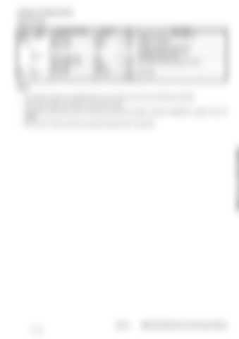
CONTROL SYSTEM (CONT’D) E-ECU (Cont’d) I/O Type Power Output supply
Input
Misc.
Misc.
Pin function/name Sensor 5V Sensor GND Sensor 12V
Symbol AVCC GND-A AVB
No. E38 E28 E43
Power supply 12V Power supply GND Power GND Boot mode -
VB GND GND-P BOOTSW -
E48 E45 E47 E29 E46
Description Voltage: Vcc0.02 V (Vcc = 5.00.1 V) Output: 25 mA Max. Voltage: Internally coupled to VB Protection against dump surge Connected to main relay Connected to battery negative terminal (Disabled)
Notes: •
The function of each pin is described later. Do not use the pins for other purposes than intended.
•
Serial communication terminal (E3, E4) cannot be used.
•
As required, jumper E30 to E39 to activate the CAN terminal resistor. See [See "HARNESS" on page 10-30-1] for details.
•
E25, E26, E27, E29, and E46 are unused terminals.Wiring is not required.
10-20-13 37 of 182
E55W, E60, E80 Electronic Control System Manual

