26 minute read
INSTRUMENTS AND CONSOLES (CONT’D)


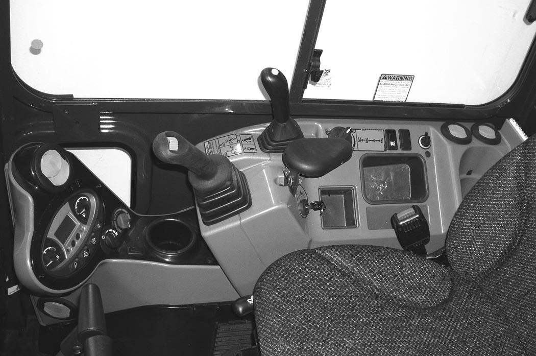
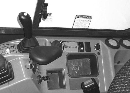
Instrument Panel - Deluxe
This machine may be equipped with a Deluxe Instrument Panel [Figure 13]
1. Keypad (1 through 0): The keypad has two functions:
- To enter a number code (password) to allow starting the engine.
- To enter a number as directed for further use of the display screen.
2. Display Screen: The display screen is where all system setup, monitoring, and error conditions are displayed.
3. Scroll Buttons: Used to scroll through display screen choices.
4. ENTER Button: Used to make selections on the display screen.
Turn the start key to the ON position.
When this screen is on the display you can enter the password and start the engine [Figure 14]
NOTE:Your excavator (with Deluxe Instrument Panel) will have an Owner Password. Your dealer will provide you with this password. Change the password to one that you will easily remember to prevent unauthorized use of your excavator. (See Changing The Owner Password on Page 212.) Keep your password in a safe location for future needs.
Enter The Password:
Use the numbers on the keypad to enter the password, then press the [ENTER] button. A symbol will appear on the display screen for each number entered. The left scroll button can be used to backspace if an incorrect number is entered.

If the correct password is not entered, [INVALID PASSWORD] will appear on the display screen and the password will have to be reentered.
See CONTROL PANEL SETUP for further description of screens to set up the system for your use. (See CONTROL PANEL SETUP on Page 205.)
Lights
Press key pad [1] [Figure 14] once for FRONT work lights. Press a second time to turn all lights off.
Change Language:
The language can be changed at any time. (See CONTROL PANEL SETUP on Page 205.)
INSTRUMENTS AND CONTROLS (CONT’D)

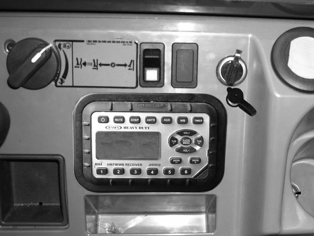
Radio Option
15
NOTE:See DISPLAY (Item 3) in the following table for clock setting instructions.
INSTRUMENT AND CONTROLS (CONT’D)
Radio (Cont’d)
REF. NO. DESCRIPTION
FUNCTION / OPERATION
1POWERPress to turn ON; press again to turn OFF.
2MUTEPress to mute audio output; [MUTE] will appear in display screen; press again to turn OFF.
3DISPLAYPress to toggle between function mode (showing tuner frequency, auxiliary input, weather band information, or timer) and clock mode. Press and hold to enter clock setting mode; use FREQUENCY DOWN (TUN -) button to adjust hours and FREQUENCY UP (TUN +) button to adjust minutes; normal operation will resume automatically.
4BANDPress to select tuner mode. Press to cycle through 2 AM (MW) bands and 3 FM bands.
5AUXILIARYPress to select Auxiliary Input mode. Portable audio device (MP3 player) must be attached to auxiliary input jack.
6WEATHER BANDPress to select weather band; use FREQUENCY UP (TUN +) and FREQUENCY DOWN (TUN -) buttons to adjust to the clearest station. The weather alert feature, if activated, will automatically switch from the current function to the weather band if a weather warning is received. See AUDIO / MENU ADJUSTMENT in this table.
7TIMERPress to access timer mode. Press to start the timer function; press again to stop timer; press again to resume timer or press and hold to reset timer and exit from timer mode.
8DISPLAY SCREENDisplays the time, frequency, and activated functions.
9VOLUME UPAdjusts volume up; current volume (0 - 40) will appear briefly in display screen.
10AUDIO / MENU ADJUSTMENT
AUDIO ADJUSTMENT: Press to cycle through bass, treble, and balance settings; use VOLUME UP (VOL +) and VOLUME DOWN (VOL -) buttons to adjust when desired option is displayed; normal operation will resume automatically.
MENU ADJUSTMENT: Press and hold for 3 seconds to enter menu adjustment settings; press to cycle through the following settings; use VOLUME UP (VOL +) and VOLUME DOWN (VOL -) buttons to adjust when desired option is displayed; normal operation will resume automatically.
• Beep Confirm (On or Off) - Determines if beep will sound with each button press.
• Operation Region (USA or Europe) - Selects the appropriate region.
• Clock Display (12 or 24) - Selects a 12-hour or 24-hour clock display.
• Display Brightness (Low, Medium, or High) - Determines brightness level of display screen.
• Backlight Color (Amber or Green) - Determines backlight color of display screen.
• Power On Volume (0 - 40) - Selects default volume setting when radio is turned on.
• WB Alert (On or Off) - Determines if weather band alert feature is activated.
11FREQUENCY DOWNPress to manually tune the radio frequency down.
12FREQUENCY UPPress to manually tune the radio frequency up.
13VOLUME DOWNAdjusts volume down; current volume (0 - 40) will appear briefly in display screen.
14SEEK FREQUENCY DOWN Press to automatically tune frequency down to next strong station.
15SEEK FREQUENCY UP Press to automatically tune frequency up to next strong station.
16PRESET STATIONSUsed to store and recall stations for each AM and FM band. Press and hold to store current station; press button to recall station.
17AUXILIARY INPUT JACK
Connect line output of portable audio device (MP3 player) to 3,5 mm (1/8 in) jack and press AUXILIARY button.
INSTRUMENT AND CONTROLS (CONT’D)
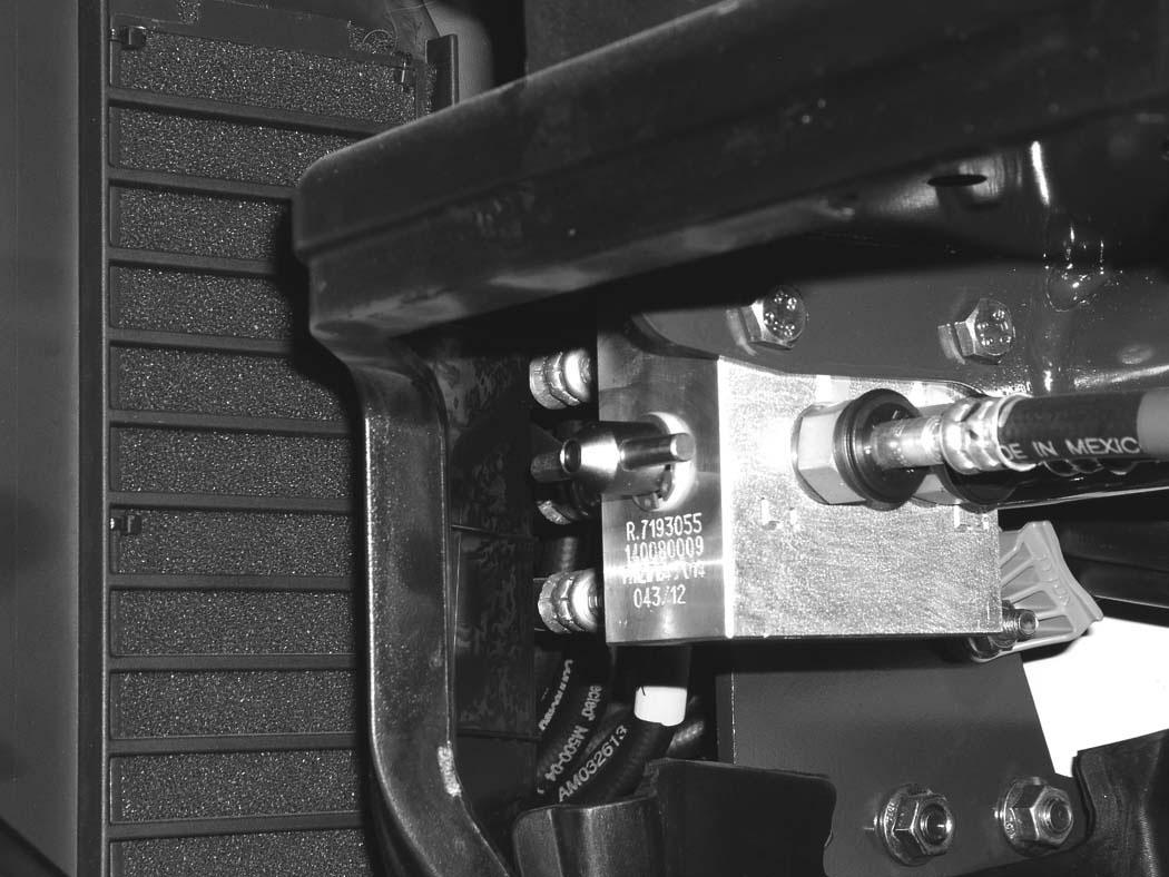
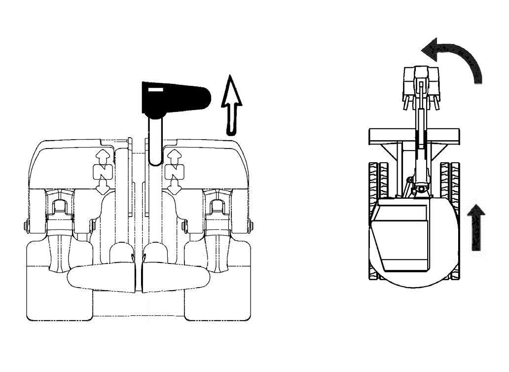
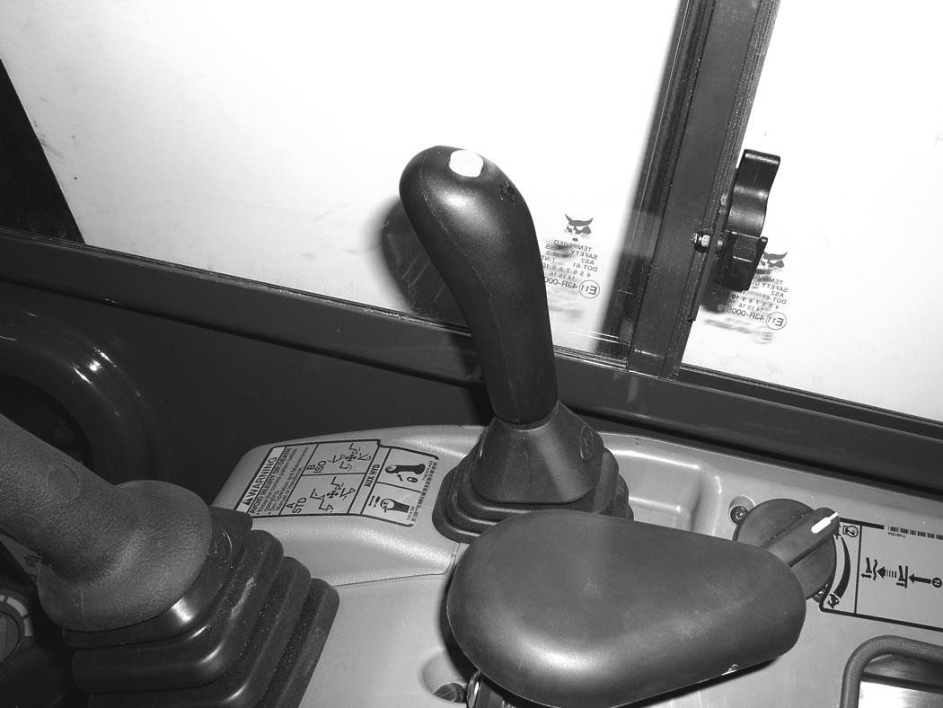
STD / ISO Selector Valve
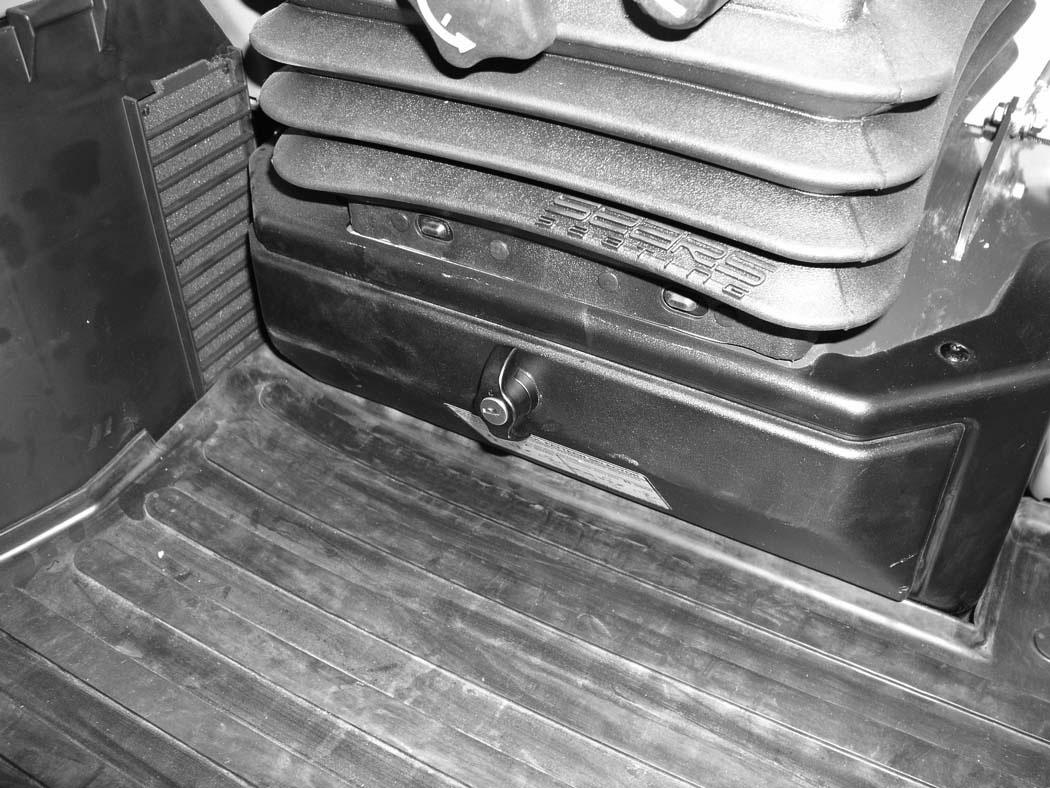
The STD / ISO selector valve is located below the operator’s seat, inside the tool box.
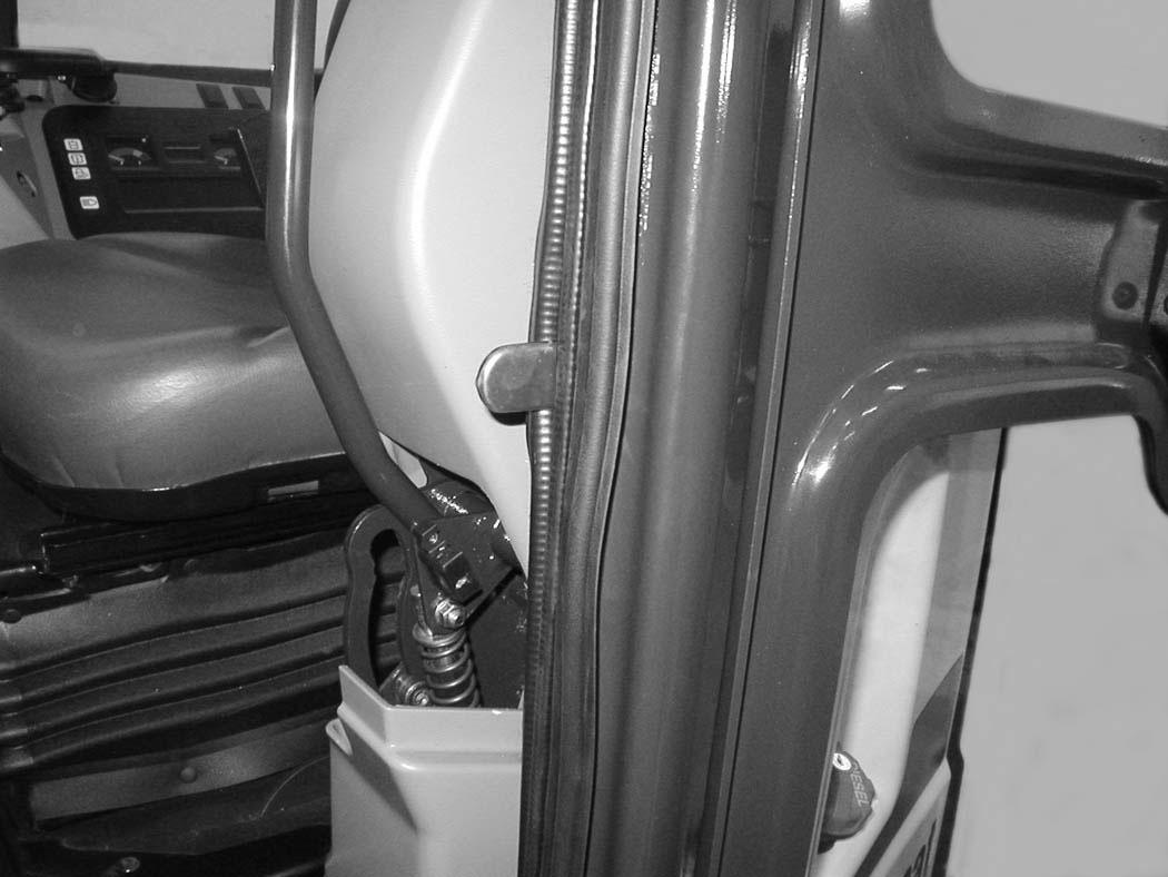
Raising And Lowering The Console
Raise the console before exiting the cab.
Figure 19
From below the operator’s seat, open the tool box cover (Item 1) [Figure 17].
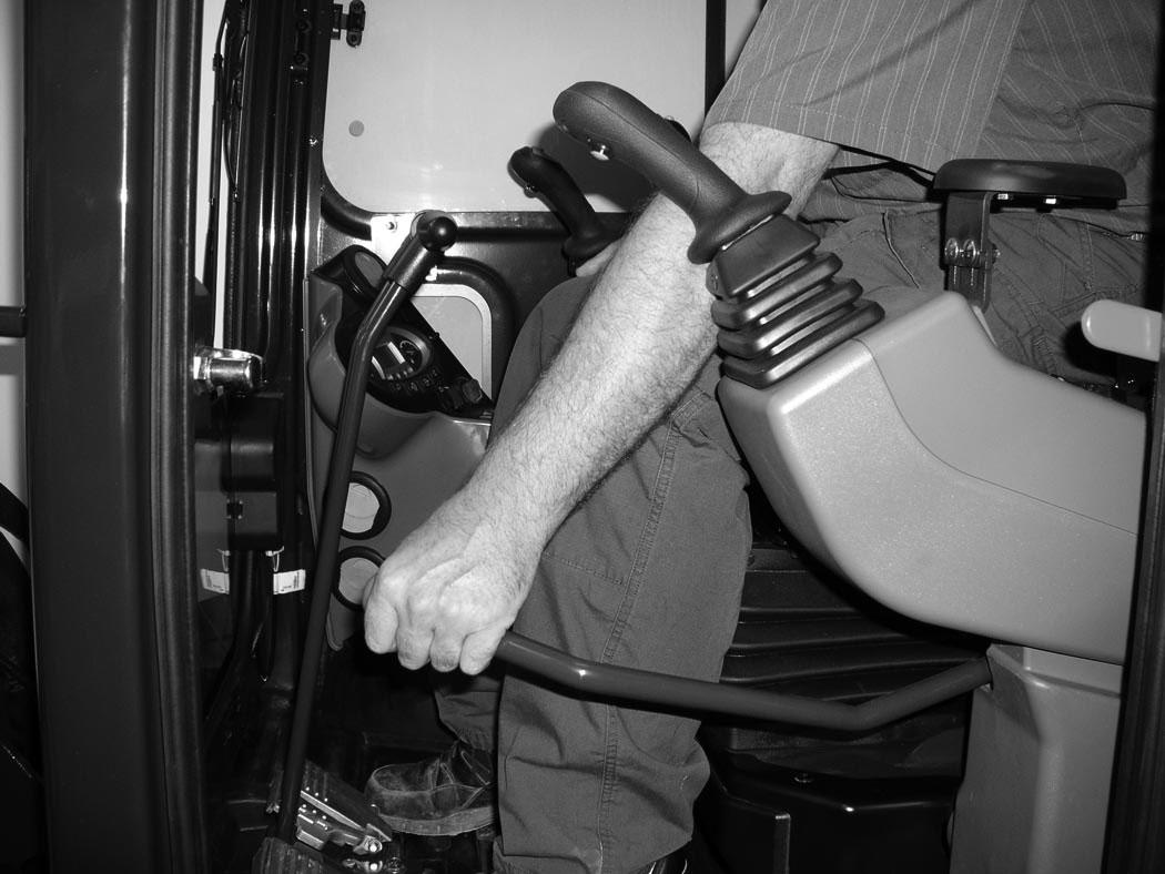
Pull up on the release handle [Figure 19]. The lift spring will assist in raising the console.
Lower the console before operating the excavator.
Push down on the lever [Figure 19] until the latch is engaged.
NOTE:When the console is raised, the hydraulic and traction system functions are locked and will not operate.
If the engine stops, the boom / bucket (attachments) can be lowered to the ground using hydraulic pressure in the accumulator.
The control console must be in the locked down position, and the key switch in the ON position.
The joystick hydraulic function can be switched from Standard control pattern to ISO control pattern.
Rotate the lever (Item 1) counterclockwise (Item 2) to select STANDARD Control Pattern. Rotate the lever clockwise (Item 3) to select ISO Control Pattern [Figure 18]
INSTRUMENT AND CONTROLS (CONT’D)


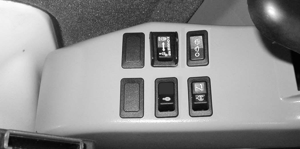
Two-Speed Travel (Without Angle Blade Option)
Figure 20
Press the button (Item 1) [Figure 20] to engage the high range. Press a second time to disengage.
Figure 21
When high range is engaged, the two speed travel icon (Item 1) [Figure 21] will illuminate.
Press the button (Item 1) [Figure 20] again to disengage.
Two-Speed Travel (With Angle Blade Option)
Figure 22
Press the button (Item 1) [Figure 22] to engage the high range. Press a second time to disengage.
Figure 23
When high range is engaged, the two speed travel icon (Item 1) [Figure 23] will illuminate.
Press the button (Item 1) [Figure 22] again to disengage.
Auto-Shift Drive System
When in high range, the travel motors will automatically shift to low range when more torque is required and return to high range when hydraulic pressure decreases.
NOTE:Always set the travel speed to low range when loading or unloading the excavator onto a transport vehicle.
INSTRUMENTS AND CONSOLES (CONT’D)
Auto Idle Feature
The auto idle feature (when engaged) will reduce the engine speed to low idle when the control levers (joystick, blade, travel, etc.) are in NEUTRAL and not used for approximately four seconds. The engine rpm will return to the set position as soon as any control lever is activated.


The automatic idle switch (Item 1) [Figure 24] is used to engage or disengage the automatic idle feature.
Press the switch (Item 1) once to engage automatic idle and the LED (Item 2) will illuminate. Press the switch (Item 1) a second time to disengage automatic idle, the LED (Item 2) [Figure 24] will be OFF.
NOTE:Always disengage the auto idle feature when loading or unloading the excavator onto a transport vehicle.
Press ENTER (Item 1) once to engage automatic idle. Press ENTER (Item 1) [Figure 25] again and auto idle will be OFF.
NOTE:Always disengage the auto idle feature when loading or unloading the excavator onto a transport vehicle.
NOTE:When equipped with the deluxe instrument panel, the time delay for auto idle to activate can be adjusted. (See Auto Idle Time Delay on Page 207.)
OPERATOR CANOPY (ROPS / TOPS)
Description
The Bobcat excavator has an operator canopy (ROPS / TOPS) as standard equipment to protect the operator if the excavator is tipped over. The seat belt must be worn for ROPS / TOPS protection.
Check the ROPS / TOPS canopy, mounting, and hardware for damage. Never modify the ROPS / TOPS canopy. Replace the canopy and hardware if damaged. See your Bobcat dealer for parts.
ROPS / TOPS - Roll-Over Protective Structure per ISO 12117-2, and Tip-Over Protective Structure per ISO 12117.
Warning
Never modify operator cab by welding, grinding, drilling holes or adding attachments unless instructed to do so by Bobcat Company. Changes to the cab can cause loss of operator protection from rollover and falling objects, and result in injury or death.
W-2069-0200
OPERATOR CAB (ROPS / TOPS)
Description
The Bobcat excavator has an optional operator cab (ROPS / TOPS) as standard equipment to protect the operator if the excavator is tipped over. The seat belt must be worn for ROPS / TOPS protection.
Check the ROPS / TOPS cab, mounting, and hardware for damage. Never modify the ROPS / TOPS cab. Replace the cab and hardware if damaged. See your Bobcat dealer for parts.
ROPS / TOPS - Roll-Over Protective Structure per ISO 12117-2, and Tip-Over Protective Structure per ISO 12117.
Warning
Never modify operator cab by welding, grinding, drilling holes or adding attachments unless instructed to do so by Bobcat Company. Changes to the cab can cause loss of operator protection from rollover and falling objects, and result in injury or death.
W-2069-0200
OPERATOR CAB (ROPS / TOPS) (CONT’D)
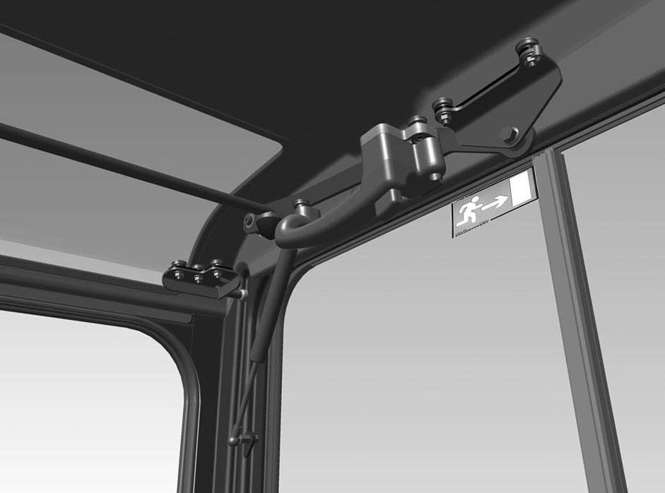
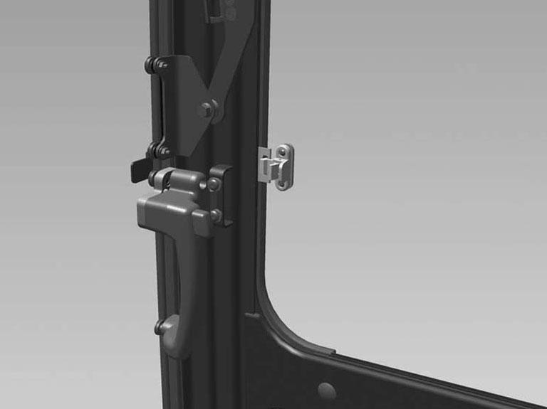
Cab Door
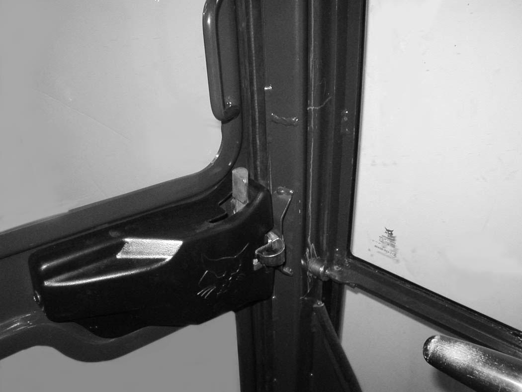
26
be
When the door is in the open position, push down on the
OPERATOR CAB (ROPS / TOPS) (CONT’D)
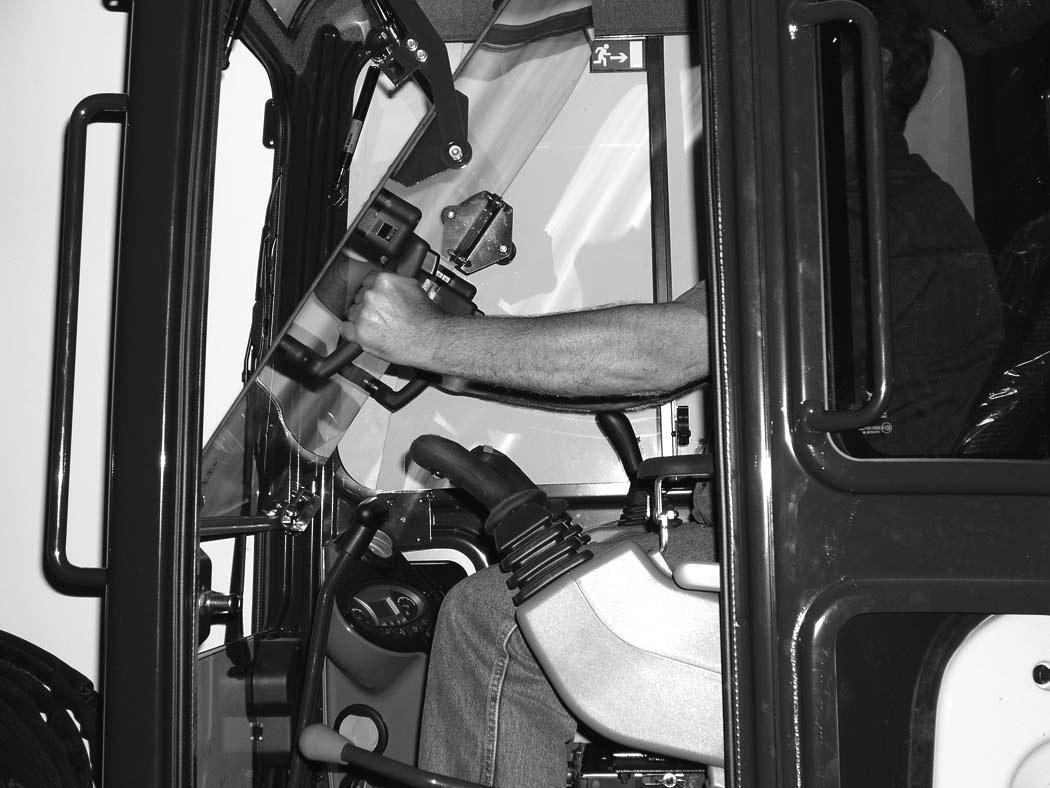
Front Window
Opening The Front Window
Figure 30
Press the window latch button (Item 1) [Figure 30] (both sides).
When the window is fully raised, the latch (Item 1) [Figure 32] (both sides) will close on the bracket in the latched position.
Pull down and forward slightly on the window to make sure it is fully latched.
Closing The Front Window
Use both window grab handles to support the window while pressing the window latch button (Item 2) [Figure 32] (both sides).
Use both window grab handles (Item 1) [Figure 31] to pull the window down fully.
Press the top of the window in until the latch locks into the latched position (both sides) [Figure 30]
Pull inward and upward slightly on the window to make sure it is fully latched in the closed position.
Use both window grab handles (Item 1) [Figure 31] to pull the top of the window in.
Continue moving the window in and up over the operator’s head until the window is fully raised.
OPERATOR CAB (ROPS / TOPS) (CONT’D)
Front Wiper
Figure 33
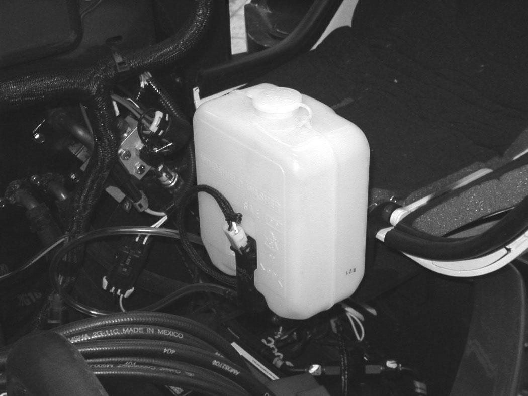
Window Washer Reservoir
Figure 34

OPERATOR CAB (ROPS / TOPS) (CONT’D)

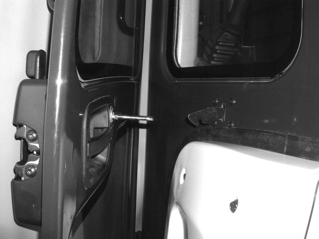
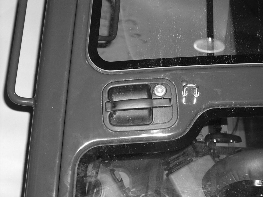
Right Side Window
Opening The Right Rear Window
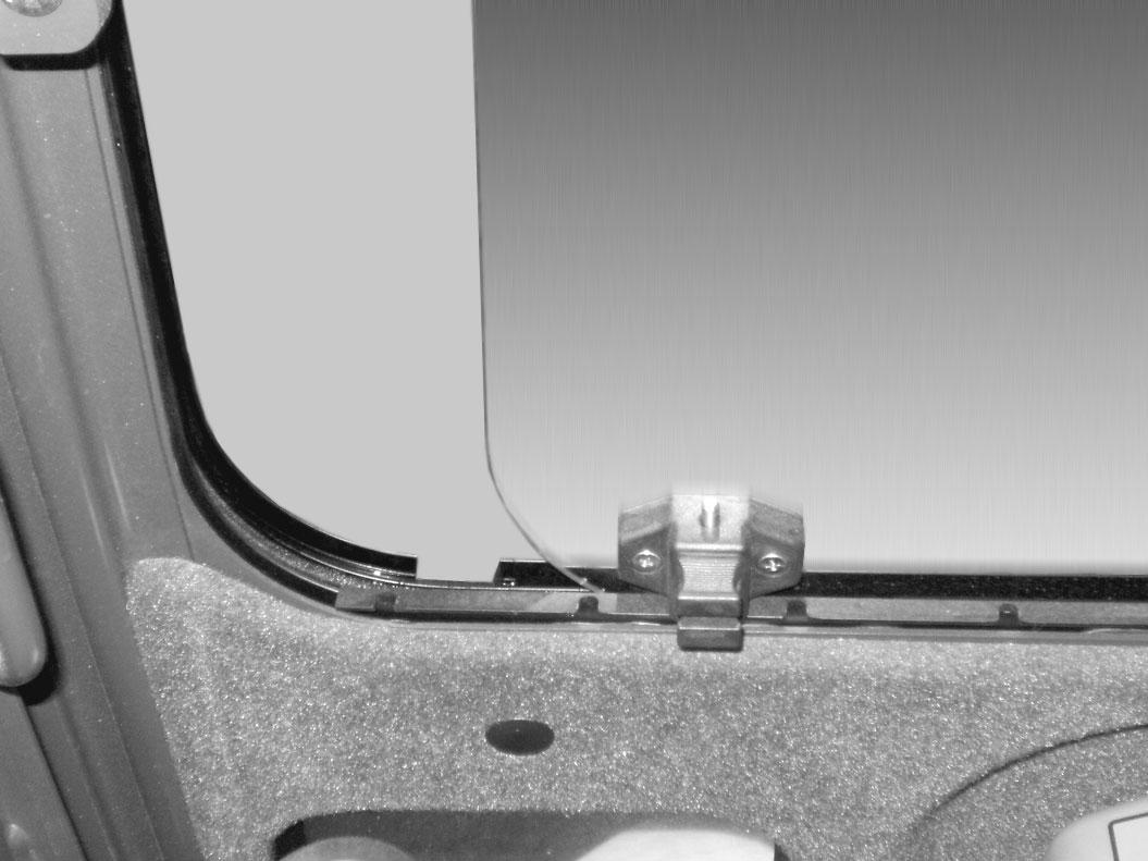


Figure 35
Pull up on the bottom latch (Item 1) [Figure 35]
Opening The Right Front Window
Figure 37
Pull the latch (Item 1) [Figure 36] forward to open the window until the desired stop. Release the bottom latch and snap the lock in place.
Closing The Right Rear Window
Pull up on the bottom latch (Item 1) [Figure 35] and push the latch back to close the window.
Pull up on the bottom latch (Item 1) [Figure 37] located at the front of the front window.
Pull the latch (Item 1) [Figure 38] forward to open the window until the desired stop. Release the bottom latch and snap the lock in place.
Closing The Right Front Window
Pull up on the bottom latch (Item 1) [Figure 37] and push the latch back to close the window.
OPERATOR CAB (ROPS / TOPS) (CONT’D)
Heating, Ventilation, And Air Conditioning Ducting
39
Emergency Exit
The door, the right side rear window and the front window provide exits.
Right Side Rear Window
Figure 40
Exit through the window [Figure 40]
Front Window
Figure 41
Open the front window and exit [Figure 41].
NOTE:If the excavator has a Special Applications Kit installed, the front window is NOT an emergency exit.


MOTION ALARM SYSTEM Operation
This excavator may be equipped with a motion alarm system. The motion alarm (Item 1) [Figure 42] is located inside the rear of the excavator.

This machine is equipped with a motion alarm. ALARM MUST SOUND! when operating forward or backward.
Failure to maintain a clear view in the direction of travel could result in serious injury or death.
The operator is responsible for the safe operation of this machine.
The motion alarm will sound when the operator moves the travel control levers (Item 1) [Figure 44] in either the forward or reverse direction.
If alarm does not sound or for adjustment instructions, see inspection and maintenance instructions for the motion alarm system in the preventive maintenance section of this manual. (See MOTION ALARM SYSTEM on Page 157.)
The motion alarm can be temporarily disabled by pressing the motion alarm switch (Item 1) [Figure 43] while the machine is moving. As soon as the travel levers are returned to the NEUTRAL position, the motion alarm will be enabled.
Travel Controls
Forward And Reverse Travel
NOTE: The following procedures describe forward, reverse, left and right as seated in the operator’s seat.
Turning Right Turn
Figure 45
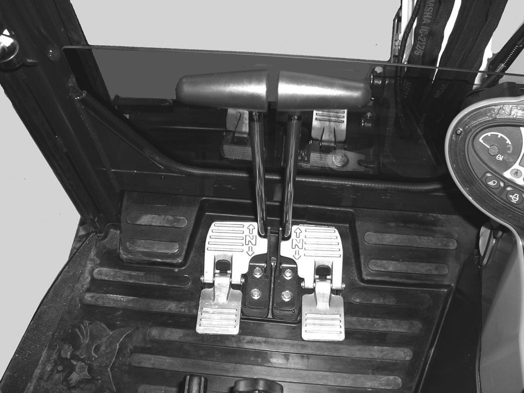
Put the blade so that it is at the front of the machine (as you sit in the operator’s seat). Slowly move both steering levers* (Item 1) [Figure 44] forward for forward travel; backward for reverse travel.
* Travel can also be controlled with foot pedals (Item 2) [Figure 44]. Pivot the heel of the pedals forward for additional space on the floor.
Warning
AVOID INJURY OR DEATH
•Check the blade location before traveling. When the blade is to the rear, operate the steering levers / foot pedals in the opposite direction to when the blade is in the front.
•Move the steering levers / foot pedals slowly. Abrupt lever motion will cause the machine to jerk.
W-2235-0396
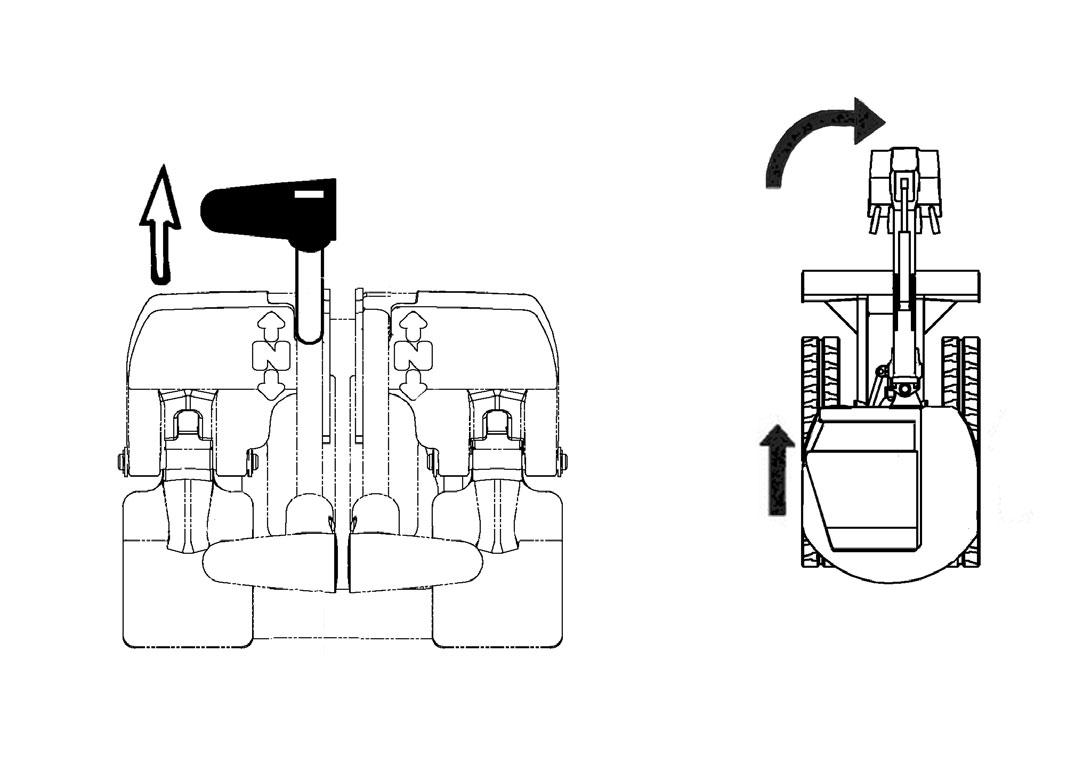
Push the left steering lever forward to turn right [Figure 45] while traveling forward.
Figure 46
Pull the left steering lever backward to turn right while traveling backward [Figure 46].
TRAVEL CONTROLS (CONT’D)
Turning (Cont’d)
Counter-Rotation Right Turn
Figure 47
Counter-Rotation (Right Turn)
Figure 49
Left Turn (Reverse)
Push the left steering lever forward and pull the right steering lever backward [Figure 47]
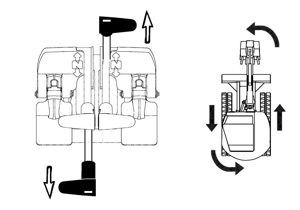

Left Turn
Figure 48
Left Turn (Forward)
NA1461A
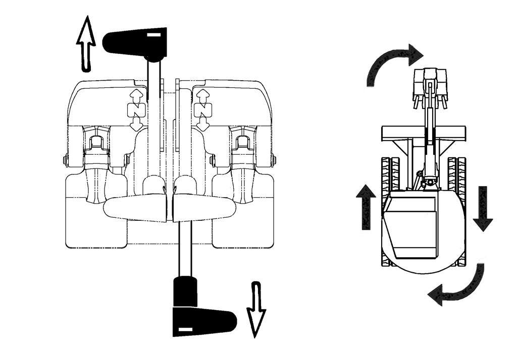
Pull the right steering lever backward to turn left while traveling backward [Figure 49]
Counter-Rotation Left Turn
Figure 50
Counter-Rotation (Left Turn)
NA1460A
Push the right steering lever forward to turn left while traveling forward [Figure 48]
Push the right steering lever forward and pull the left steering lever backward [Figure 50]
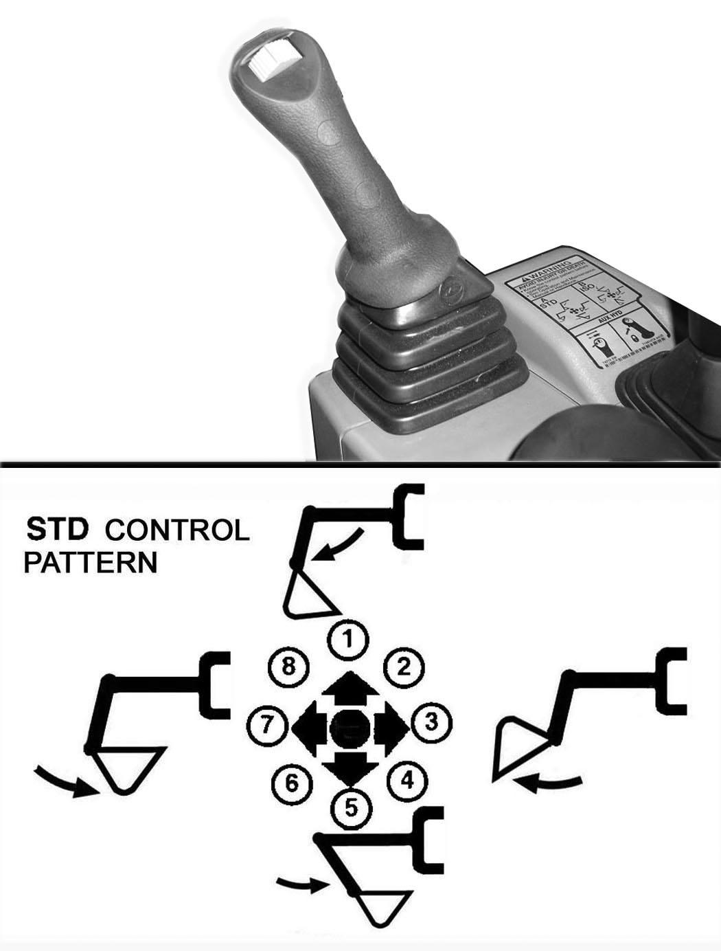
HYDRAULIC CONTROLS Description
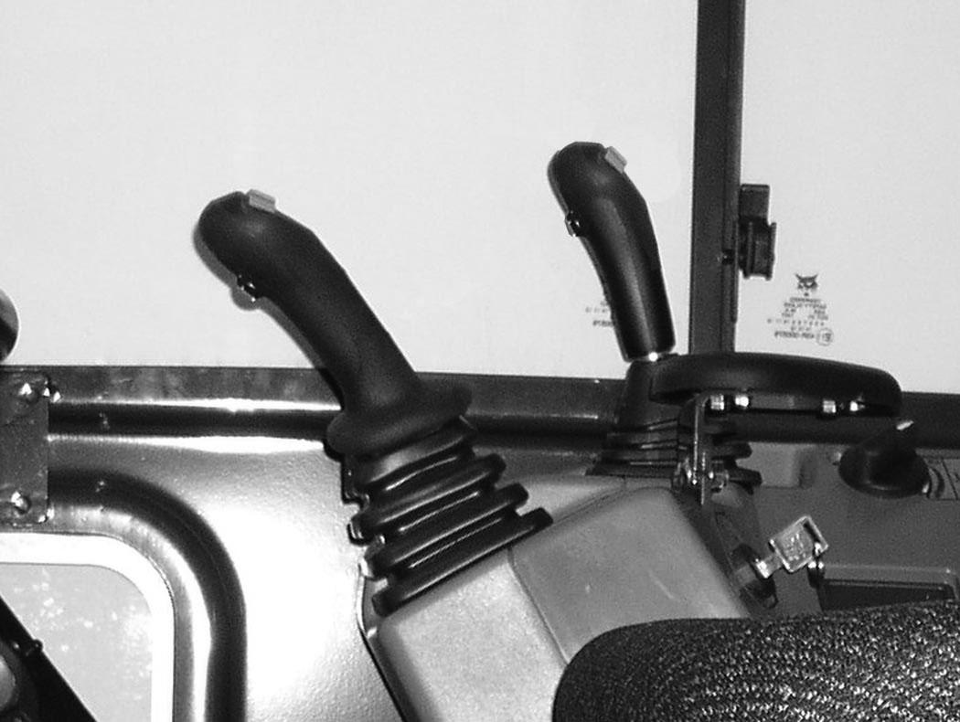
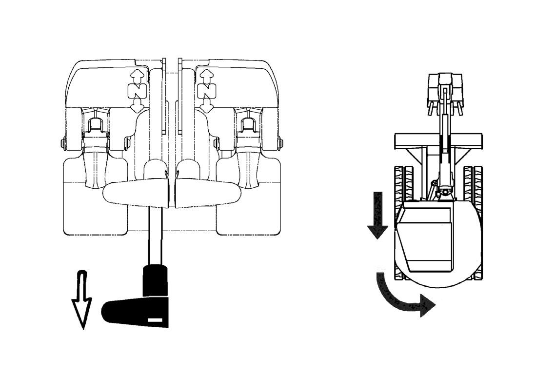
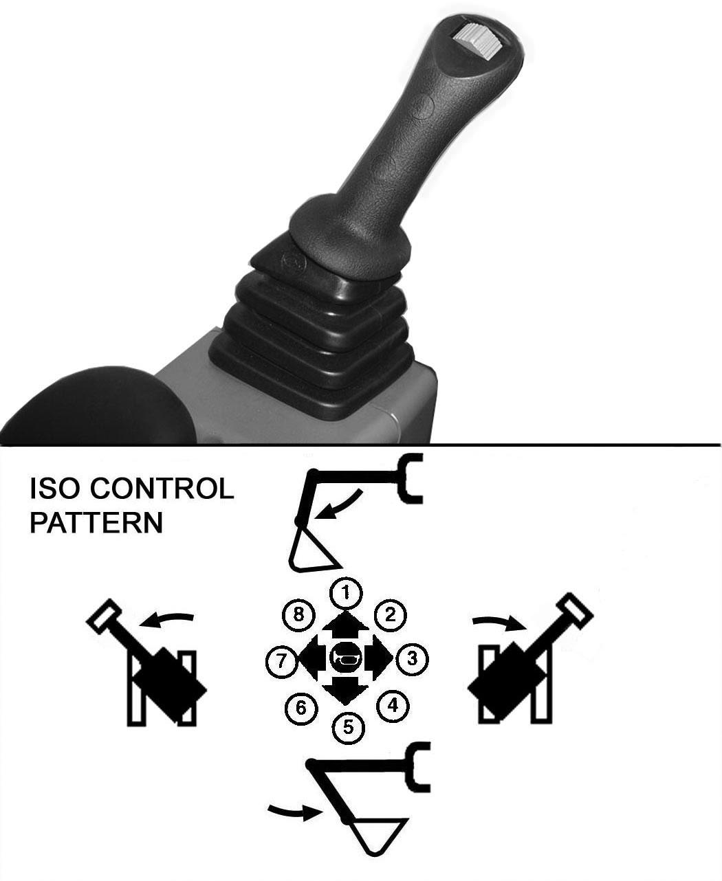
The work equipment (boom, arm, bucket, and upperstructure slew) is operated by using the left and right control levers (joysticks). These joysticks can be used in either a STANDARD Control Pattern [Figure 51] and [Figure 52] or in the ISO Control Pattern [Figure 53] and [Figure 54]
STANDARD Control Pattern
Left Control Lever (Joystick)
Figure 51
P113002A
The left lever (joystick) is used to operate the boom and slew the upperstructure [Figure 51]
1. Boom lower.
2. Boom lower and slew right.
3. Slew right.
4. Boom raise and slew right.
5. Boom raise.
6. Boom raise and slew left.
7. Slew left.
8. Boom lower and slew left.
Right Control Lever (Joystick)
Figure 52
P113003A
The right lever (joystick) is used to operate the arm and bucket [Figure 52]
1. Arm out.
2. Arm out and bucket dump.
3. Bucket dump.
4. Arm in and bucket dump.
5. Arm in.
6. Arm in and bucket curl.
7. Bucket curl.
8. Arm out and bucket curl.
Warning
AVOID INJURY OR DEATH
Before leaving the machine:
•Lower the work equipment to the ground.
•Lower the blade to the ground.
•Stop the engine and remove the key.
•Raise the control console. W-2780-0109
HYDRAULIC CONTROLS (CONT’D)
ISO Control Pattern
Left Control Lever (Joystick)
Figure 53
The left lever (joystick) is used to operate the arm and slew the upperstructure [Figure 53].
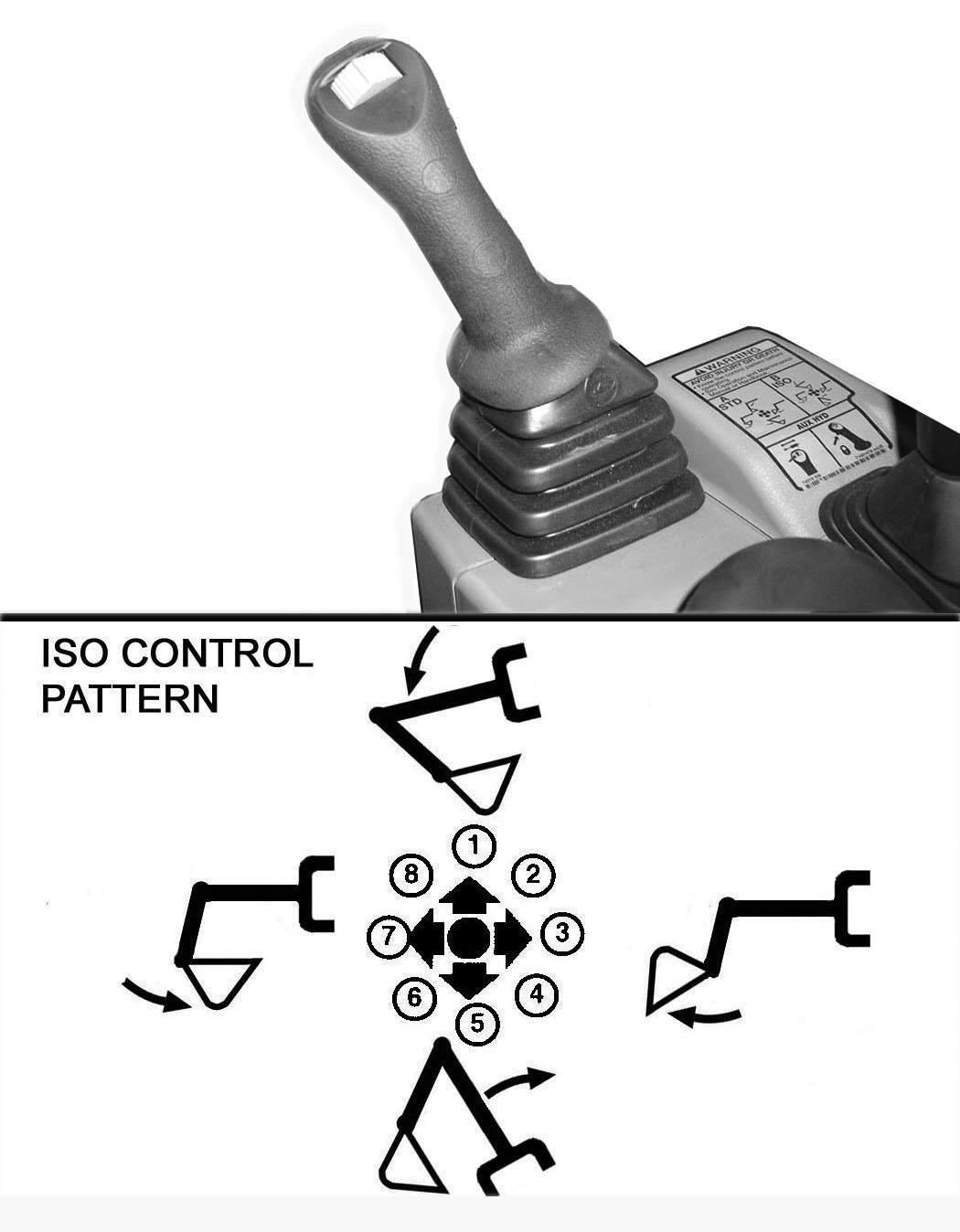
1. Arm out.
2. Arm out and slew right.
3. Slew right.
4. Arm in and slew right.
5. Arm in.
6. Arm in and slew left.
7. Slew left.
8. Arm out and slew left.
Right Control Lever (Joystick)
Figure 54
The right lever (joystick) is used to operate the boom and bucket [Figure 54]
1. Boom lower.
2. Boom lower and bucket dump.
3. Bucket dump.
4. Boom raise and bucket dump.
5. Boom raise.
6. Boom raise and bucket curl.
7. Bucket curl.
8. Boom lower and bucket curl. WARNING
AVOID INJURY OR DEATH
Before leaving the machine:
•Lower the work equipment to the ground.
•Lower the blade to the ground.
•Stop the engine and remove the key.
•Raise the control console.
W-2780-0109
HYDRAULIC CONTROLS (CONT’D)
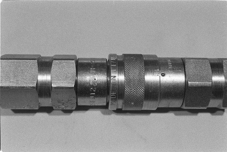
Quick Couplers
Warning
AVOID BURNS
Hydraulic fluid, tubes, fittings and quick couplers can get hot when running machine and attachments. Be careful when connecting and disconnecting quick couplers.
W-2220-0396
Warning
AVOID INJURY OR DEATH
Diesel fuel or hydraulic fluid under pressure can penetrate skin or eyes, causing serious injury or death. Fluid leaks under pressure may not be visible. Use a piece of cardboard or wood to find leaks. Do not use your bare hand. Wear safety goggles. If fluid enters skin or eyes, get immediate medical attention from a physician familiar with this injury.
W-2072-0807
To Connect:
Remove any dirt or debris from the surface of both the male and female couplers, and from the outside diameter of the male coupler. Visually check the couplers for corroding, cracking, damage, or excessive wear, if any of these conditions exist, the coupler(s) (Item 1) [Figure 55] must be replaced.
Install the male coupler into the female coupler. Full connection is made when the ball release sleeve slides forward on the female coupler.
To Disconnect:
Figure 56
Excavators and attachments are supplied with flush faced couplers (Item 1) [Figure 55]
Hold the male coupler (Item 1). Retract the sleeve (Item 2) [Figure 56] on the female coupler until the couplers disconnect.

HYDRAULIC CONTROLS (CONT’D)
Auxiliary Hydraulics - Standard Instrument Panel
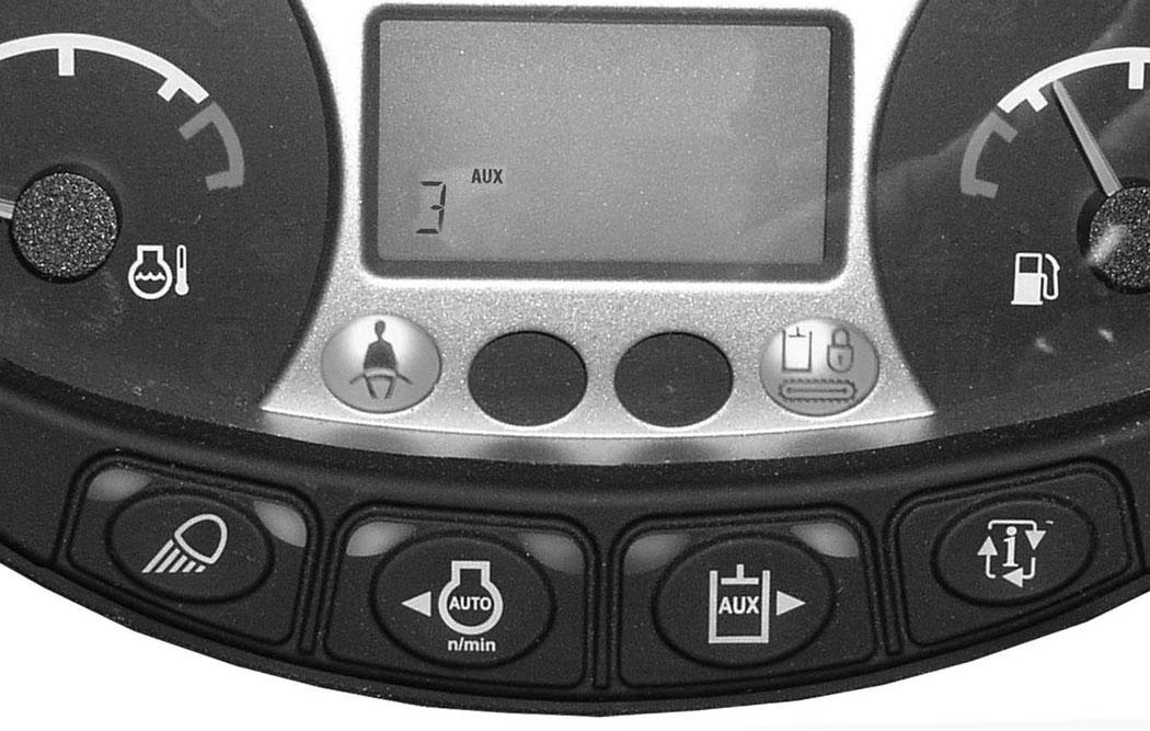
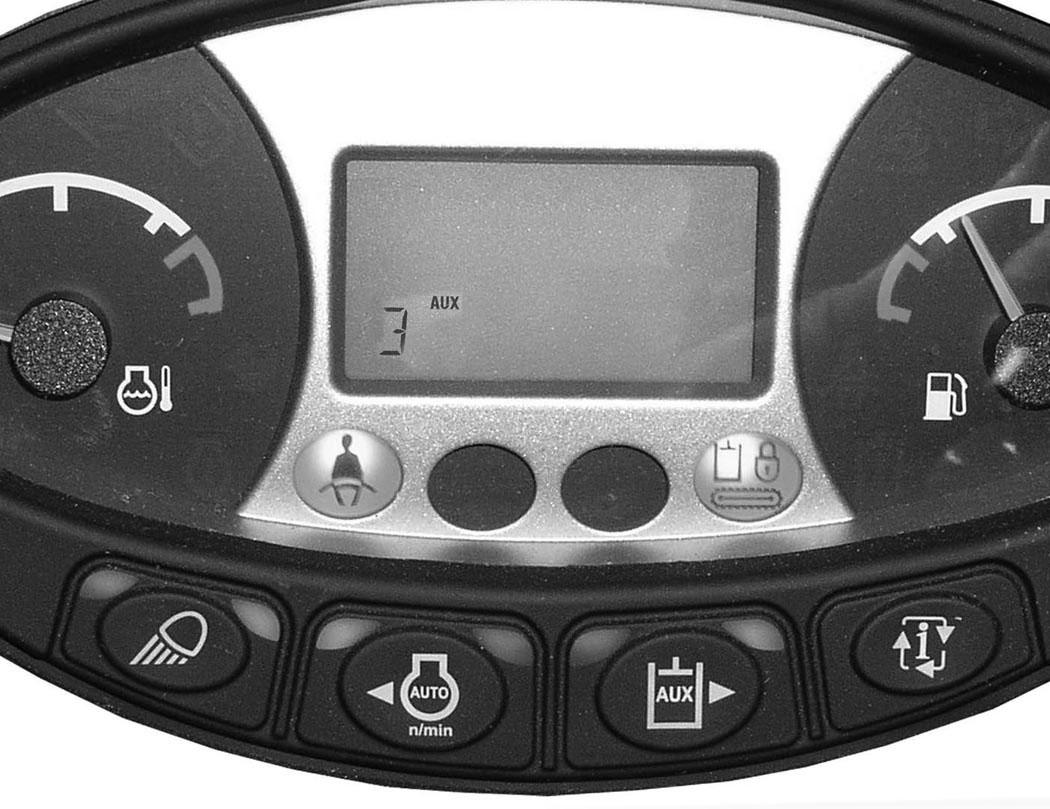
The primary auxiliary hydraulics has Selectable Auxiliary Hydraulic Flow or Continuous Auxiliary Hydraulic Flow. This allows the operator to select a hydraulic flow that matches the attachment hydraulic requirements. The auxiliary hydraulics can be set to Aux3, Aux2, Aux1 or OFF. Aux3 allows maximum hydraulic flow, Aux2 allows medium hydraulic flow and Aux1 allows low hydraulic flow.
Examples For Setting Selectable Auxiliary Hydraulic Flow And The Attachment Used:
Aux Flow Setting Flow Attachments
Aux3MaximumBreaker, Vibratory Plate Compactor, Auger Aux2MediumClamp, Grapple Aux1LowPower Tilt, Hydra Tilt
NOTE:Use only approved attachments for your model excavator. Attachments are approved for each model of excavator based on various factors. Using unapproved attachments could cause damage to the attachment or to the excavator.
NOTE:If the auxiliary hydraulics are enabled when the engine is turned OFF, they will stay enabled when the engine is restarted. If Continuous Flow was enabled at engine OFF, it will reset to selectable flow mode.
Selectable Auxiliary Hydraulics Flow - Press the Auxiliary Hydraulics button (Item 1) (an audible beep will sound each time the auxiliary button is pressed). The last selected auxiliary hydraulic flow (Aux3, Aux2 or Aux1) will appear in the data display (Item 2). The LED (Item 3) [Figure 57] will be illuminated.
To change the auxiliary flow, press the Auxiliary Hydraulics button (Item 1) to toggle through the settings, each time the button is pressed, the next setting will appear in the data display (Item 2) [Figure 57]. Once the desired setting is selected, it will stay at that setting until a different auxiliary flow is selected by the operator. (Example: Even if the engine was STOPPED, if Aux2 has been selected, after key OFF and engine restart, the Aux2 setting will still be the active hydraulic flow when the machine is started.)
Continuous Flow Auxiliary Hydraulics - Press and hold the Auxiliary Hydraulics button (Item 1) for more than one second. The LED (Item 4) will illuminate. Press the Auxiliary Hydraulics button (Item 1) [Figure 57] again to scroll through the various continuous flow auxiliary hydraulic settings (3, 2, 1).
Move the switch (Item 1) [Figure 58] on the right control lever to the right to supply hydraulic flow to the female coupler. Move the switch to the left to supply hydraulic flow to the male coupler. If you move the switch halfway, the auxiliary functions move at approximately one-half speed.
Press the button (Item 2) [Figure 58] on the front of the handle to provide continuous flow to the female coupler.
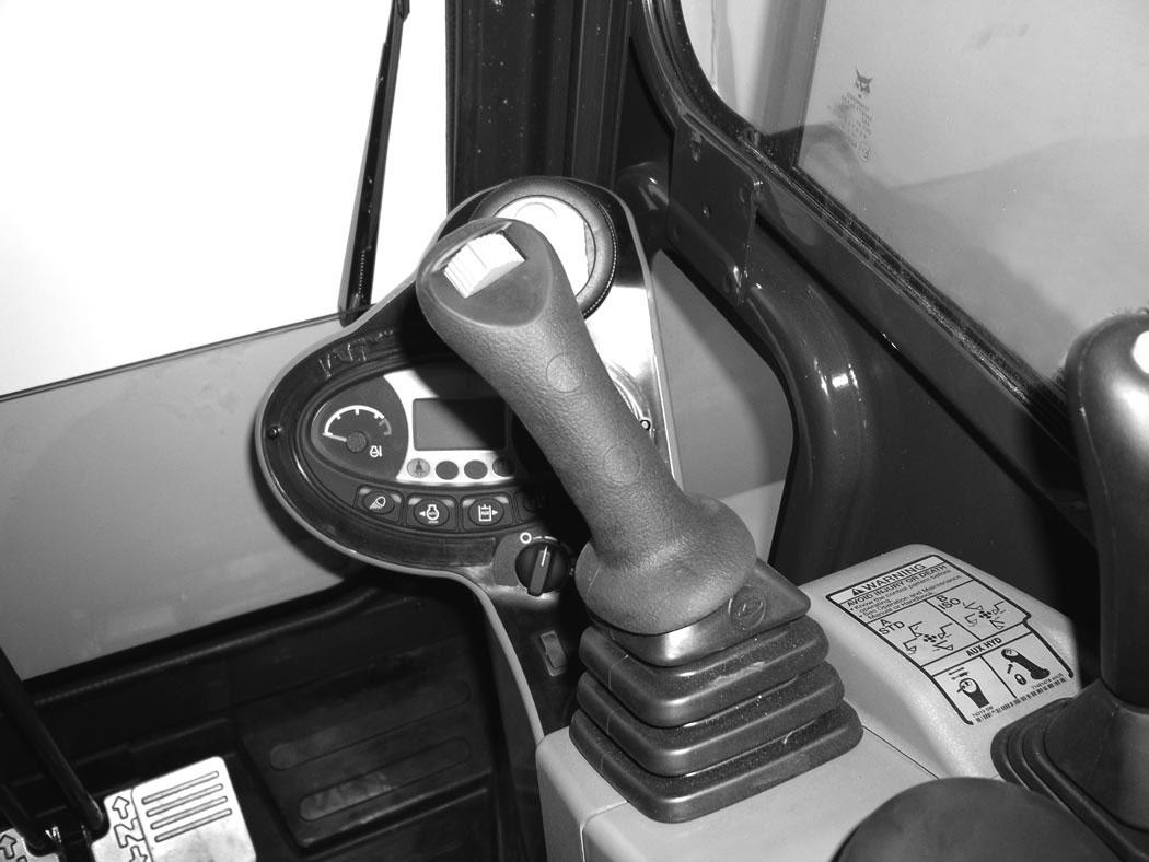
NOTE: Pressing the switch (Item 1) to the left while pressing the button (Item 2) [Figure 58] on the front of the handle will provide continuous flow to the male coupler.
Press the button (Item 2) [Figure 58] a second time to stop auxiliary flow to the quick couplers.
NOTE:Reverse flow can cause damage to some attachments. Use reverse flow with your attachment only if approved. See your attachment Operation & Maintenance Manual for detailed information.
HYDRAULIC CONTROLS (CONT’D)
Auxiliary Hydraulics - Deluxe Instrument Panel

The primary auxiliary hydraulics has Selectable Auxiliary Hydraulic Flow or Continuous Auxiliary Hydraulic Flow. This allows the operator to select a hydraulic flow that matches the attachment hydraulic requirements. The auxiliary hydraulics can be set to Aux3, Aux2, Aux1 or OFF. Aux3 allows maximum hydraulic flow, Aux2 allows medium hydraulic flow and Aux1 allows low hydraulic flow.
Examples For Setting Selectable Auxiliary Hydraulic Flow And The Attachment Used:
Aux Flow Setting Flow Attachments
Aux3MaximumBreaker, Vibratory Plate Compactor, Auger
Aux2MediumClamp, Grapple
Aux1LowPower Tilt, Hydra Tilt
NOTE:Use only approved attachments for your model excavator. Attachments are approved for each model of excavator based on various factors. Using unapproved attachments could cause damage to the attachment or to the excavator.
NOTE:If the auxiliary hydraulics are enabled when the engine is turned OFF, they will stay enabled when the engine is restarted. If Continuous Flow was enabled at engine OFF, it will reset to selectable flow mode.
Selectable Flow Auxiliary Hydraulics - Press key pad [6] [Figure 59] to scroll through the various front auxiliary hydraulic settings (3, 2, 1).
Continuous Flow Auxiliary Hydraulics - Press and hold the key pad [6] [Figure 59] for more than one second. The continuous flow icons below will illuminate. Press the key pad [6] to scroll through the various continuous flow auxiliary hydraulic settings (3, 2, 1).
ICON DESCRIPTION
Engine OFF - Auxiliary Hydraulics Pressure Relieve
Engine Running - Auxiliary Hydraulics OFF
Auxiliary Hydraulics - Maximum FlowContinuous Flow Disabled
Auxiliary Hydraulics - Medium FlowContinuous Flow Disabled
Auxiliary Hydraulics - Low Flow - Continuous Flow Disabled
Auxiliary Hydraulics - Maximum FlowContinuous Flow Enabled
Auxiliary Hydraulics - Medium FlowContinuous Flow Enabled
Auxiliary Hydraulics - Low Flow - Continuous Flow Enabled
Move the switch (Item 1) [Figure 60] on the right control lever to the right to supply hydraulic flow to the female coupler. Move the switch to the left to supply hydraulic flow to the male coupler. If you move the switch halfway, the auxiliary functions move at approximately one-half speed.
Press the button (Item 2) [Figure 60] on the front of the handle to provide continuous flow to the female coupler.
NOTE: Pressing the switch (Item 1) to the left while pressing the button (Item 2) [Figure 60] on the front of the handle will provide continuous flow to the male coupler.
Press the button (Item 2) [Figure 60] a second time to stop auxiliary flow to the quick couplers.
NOTE:Reverse flow can cause damage to some attachments. Use reverse flow with your attachment only if approved. See your attachment Operation & Maintenance Manual for detailed information.
HYDRAULIC CONTROLS (CONT’D)
Relieve Hydraulic Pressure With Standard Instrument Panel (Excavator And Attachment)
Excavator:
Put the attachment flat on the ground.
Stop the engine and turn the key switch to ON.
NOTE: The left console must be fully lowered for relieving hydraulic pressure.
NOTE:Excavator engine must have recently been started to relieve hydraulic pressure.
Relieve Hydraulic Pressure With Deluxe Instrument Panel (Excavator And Attachment)
Excavator:
Put the attachment flat on the ground.
NOTE:Excavator engine must have recently been started to relieve hydraulic pressure.
If the auxiliary hydraulics are disabled, press AUX HYD Button (Item 1) [Figure 61] and then move the switch (Item 1) [Figure 60] to the right and left several times.
If the auxiliary hydraulics are enabled, then move the switch (Item 1) [Figure 60] to the right and left several times.
Attachments:
•Follow procedure above to relieve hydraulic pressure in excavator.
•Connect male coupler from attachment to female coupler of excavator then repeat procedure above. This will relieve pressure in the attachment.
•Connect the female coupler from the attachment.
Hydraulic pressure in the auxiliary hydraulic system can make it difficult to engage quick couplers to an attachment.
Stop the engine and turn the start switch to ON. Press either scroll button (Item 1) [Figure 62] (Deluxe Panel) until the above screen is visible.

Press Button [6] [Figure 62] and the [AUX PRESSURE RELEASE] screen [Figure 63] will be visible.

Press the [ENTER] button (Item 1) [Figure 63] to relieve auxiliary pressure in the excavator. An hour glass symbol will appear and when pressure is relieve, the screen will show Auxiliary Hydraulic Pressure Release
Attachments:
•Follow procedure above to relieve hydraulic pressure in excavator.
•Connect male coupler from attachment to female coupler of excavator then repeat procedure above. This will relieve pressure in the attachment.
•Connect the female coupler from the attachment.
Hydraulic pressure in the auxiliary hydraulic system can make it difficult to engage quick couplers to an attachment.
HYDRAULIC CONTROLS (CONT’D)
Secondary Auxiliary Hydraulics
If equipped with secondary auxiliary hydraulics, the second set of hydraulic couplers will be mounted on the right side of the arm.
Relieve Secondary Auxiliary Hydraulic Pressure (Excavator And Attachment)
Excavator:
Put the attachment flat on the ground.
Stop the engine and turn the key to ON.
NOTE: The left console must be fully lowered for relieving hydraulic pressure.
NOTE:Excavator engine must have recently been started to relieve hydraulic pressure.
Press AUX HYD button (Item 1) [Figure 64] and then move the switch (Item 1) [Figure 65] to the right and left several times.
Attachments:
•Follow procedure above to relieve pressure in excavator.
Press AUX HYD button (Item 1) [Figure 64] (if equipped) to the right, secondary auxiliary hydraulic position.
•Connect male coupler from attachment to female coupler of excavator then repeat procedure above. This will relieve pressure in the attachment.
•Connect the female coupler from the attachment.
Hydraulic pressure in the auxiliary hydraulic system can make it difficult to engage quick couplers to an attachment.
Move the switch (Item 1) [Figure 65] on the left control lever to the left to supply hydraulic flow to the female coupler. Move the switch to the right to supply hydraulic flow to the male coupler. If you move the switch halfway, the auxiliary functions move at approximately one-half speed.
HYDRAULIC CONTROLS (CONT’D)
Return To Tank Valve
The return to tank valve is located under the right side cover at the front of the control valve (if equipped).
OVERLOAD WARNING Description
The overload warning feature, when engaged, will alert the operator with a warning buzzer and the general warning icon on the instrument panel when the work group is overloaded.

If overload occurs, immediately bring the arm toward the machine, lower the boom and reduce the load before continuing operation.
Operation
Rotate the lever (Item 1) [Figure 66] clockwise to direct auxiliary return hydraulic fluid to the reservoir.
Rotate the lever (Item 1) [Figure 66] counterclockwise for two way hydraulic auxiliary flow operation.
Press the switch (Item 1) [Figure 67] to the right to enable the Overload Warning Feature.
A buzzer will sound and the general warning icon (Item 1) [Figure 68] will illuminate when the boom is overloaded.
To disengage the overload warning feature, press the switch (Item 1) [Figure 67] to the left. The icon (Item 1) [Figure 68] will turn off when the overload warning feature is disabled.
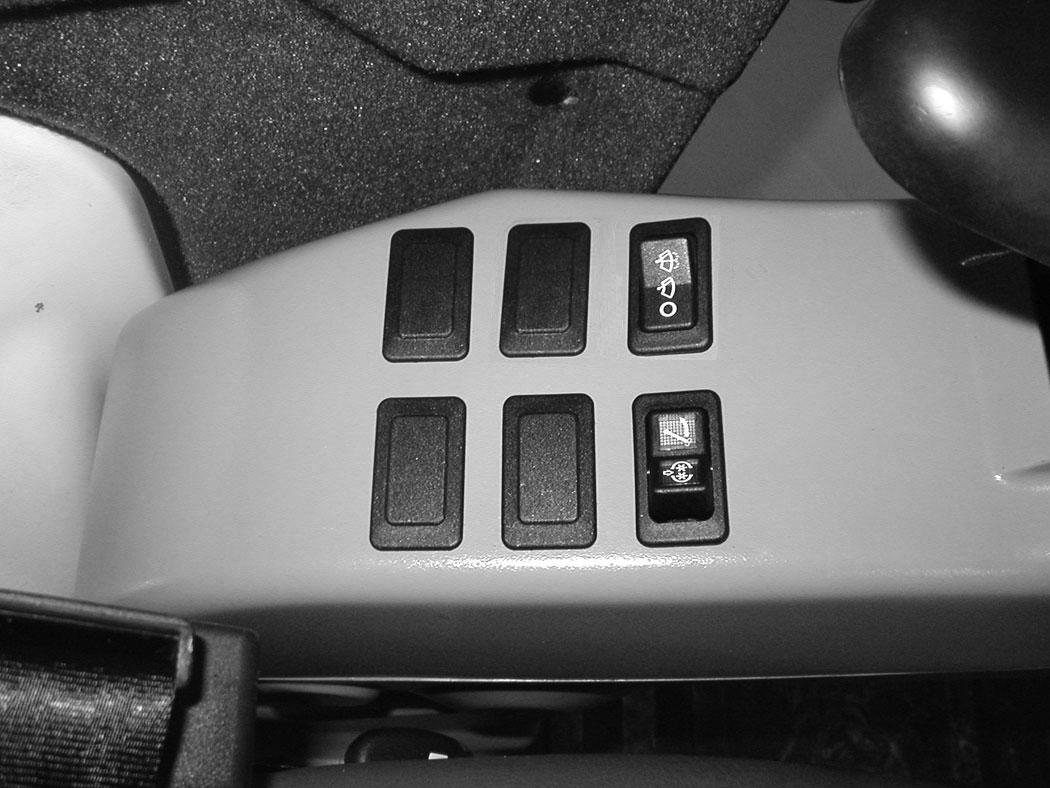
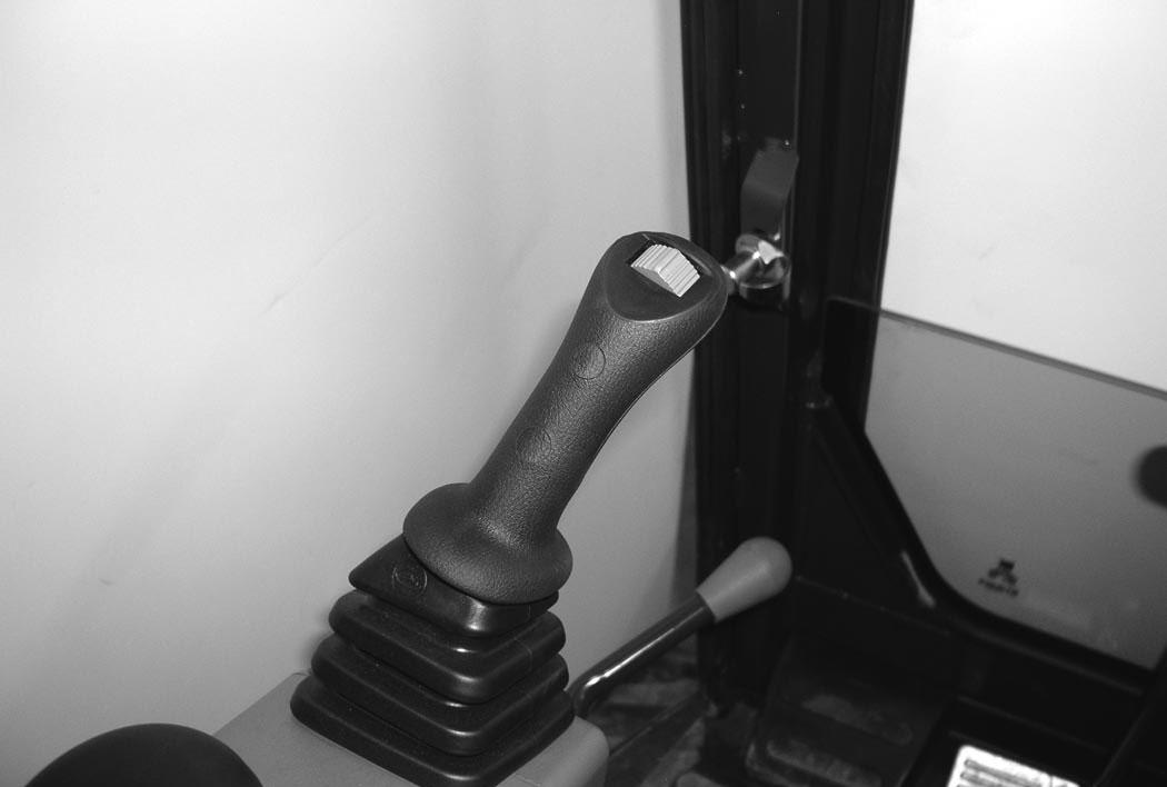
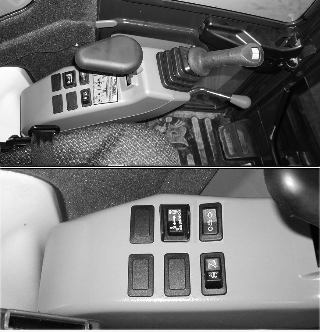
Blade Control Lever

Raising And Lowering Blade
Angling Blade (If Equipped)
NOTE:The blade lever shown in [Figure 69] is for machines without angle blade. For machines with angle blade, the blade lever is shown in [Figure 70].
Pull the lever backward to raise the blade (Item 1) [Figure 69]
Push the lever forward to lower the blade (Item 2) [Figure 69]
Push the lever (Item 3) [Figure 69] forward until the lever is in the locked position to put the blade in the float position.
Pull the lever backward to unlock from the float position.
NOTE: Keep blade lowered for increased digging performance.
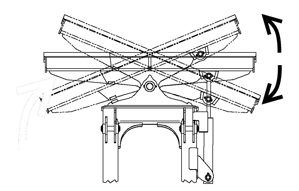
Move the switch (Item 1) [Figure 70] to the left to angle the blade to the left [Figure 71].
Move the switch (Item 1) [Figure 70] to the right to angle the blade to the right [Figure 71]
NOTE:Always have the blade straight for excavating or for lifting the excavator.
Engine Speed Control Dial
Setting Engine Speed (RPM)
72
The engine speed control dial (Item 1) [Figure 72] controls engine rpm.
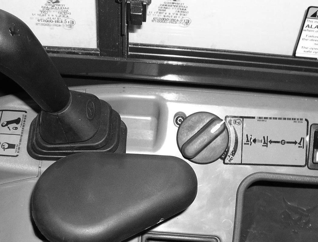
Rotate the engine speed control dial counterclockwise (Item 2) to reduce engine rpm. Rotate the engine speed control dial clockwise (Item 3) [Figure 72] to increase engine rpm.
ECO Mode (With Deluxe Instrument Panel Only)
If equipped with the Deluxe Instrument Panel, ECO mode is available.
To enable ECO mode: (See ECO MODE on Page 208.)
The switch (Item 1) [Figure 73] on the left control lever (joystick) controls boom swing. Move the switch to the left to swing the boom to the left. Move the switch to the right to swing the boom to the right.
If Equipped With Secondary Auxiliary Hydraulics:
If the machine is equipped with secondary auxiliary hydraulic couplers, the switch (Item 2) [Figure 73] is used to select either the boom swing function or the secondary auxiliary hydraulic function.
Move the switch (Item 2) [Figure 73] to the left to select boom swing function, move the switch to the right to select secondary auxiliary hydraulic function.
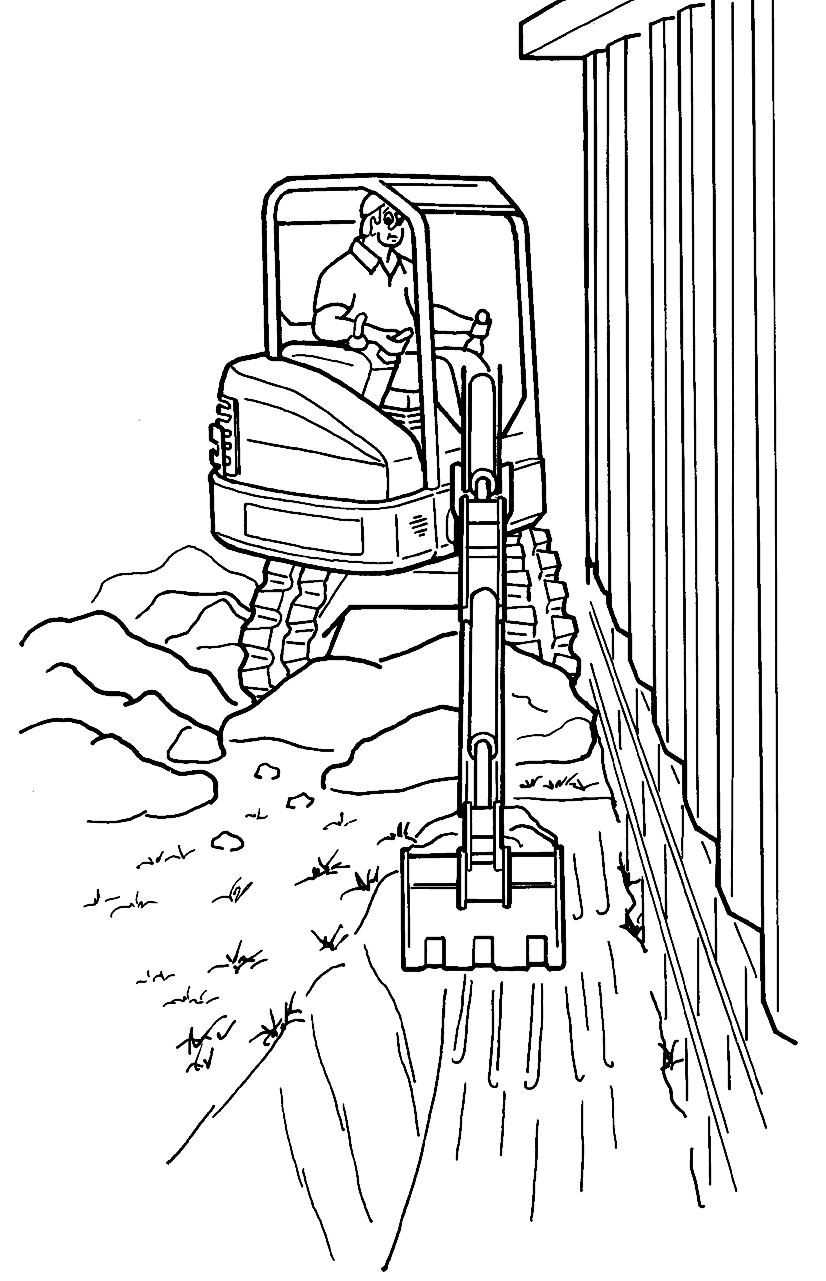
NOTE: The purpose of the boom swing is to offset the boom with respect to the upperstructure for digging close to a structure [Figure 74].
Boom Load Holding Valve
Description
The boom load holding valve (if equipped) will hold the boom in its current position in the event of hydraulic pressure loss.
Warning
AVOID INJURY OR DEATH
Do Not work or stand under raised work equipment or attachment.
Lowering Boom With Load Holding Valve
Warning
AVOID BURNS
Hydraulic fluid, tubes, fittings and quick couplers can get hot when running machine and attachments. Be careful when connecting and disconnecting quick couplers.
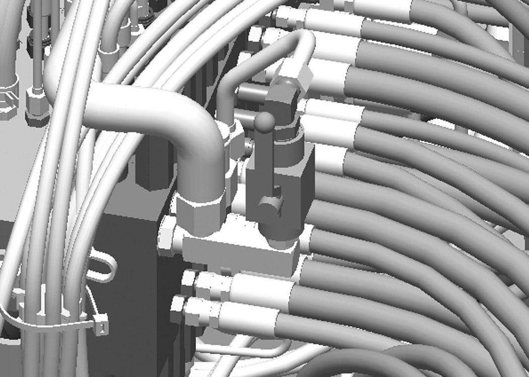
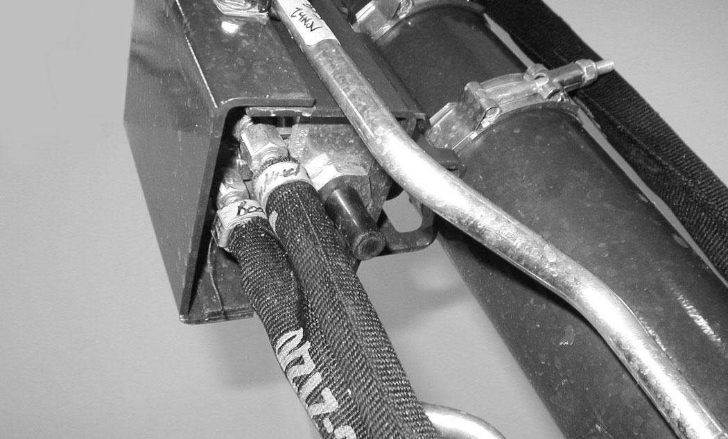
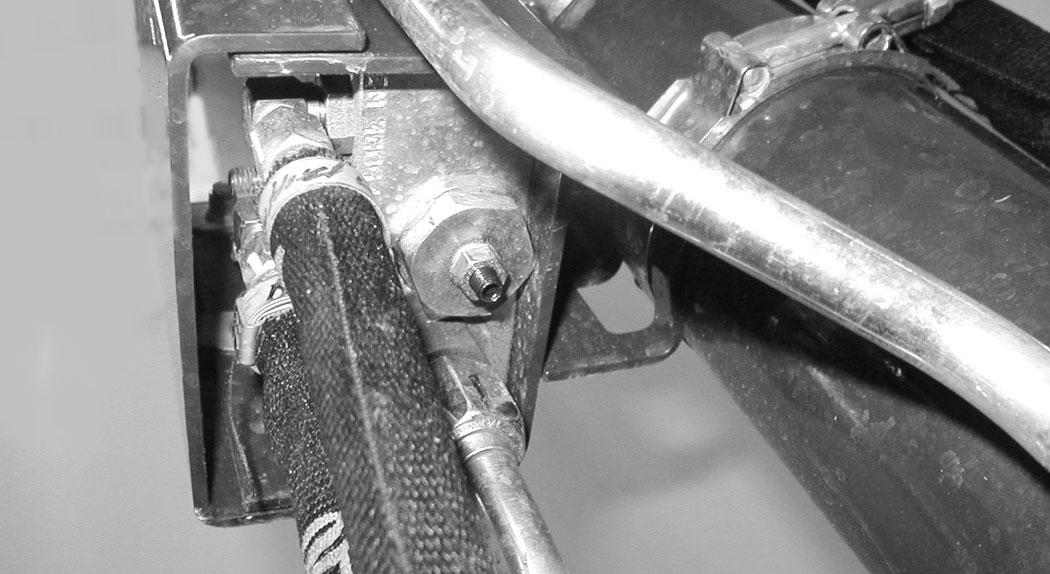
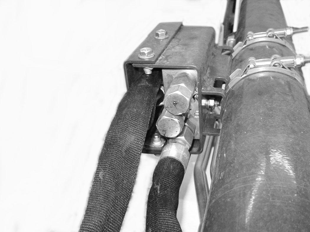
NOTE:DO NOT remove or adjust the two port relief valves (Item 2) [Figure 75]. If the port relief valves have been tampered with, see your Bobcat dealer for service.
BOOM LOAD HOLDING VALVE (CONT’D)
Lowering Boom With Load Holding Valve (Cont’d)
Figure 77
Loss of hydraulic pressure:
Use the same procedure as: With rod end hose failure and NO accumulator pressure
Lowering procedures:
With base end hose failure:
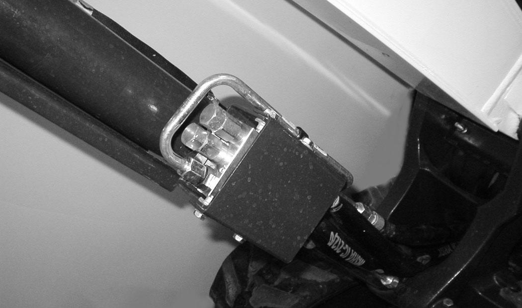
Loosen the locknut (Item 1). Install a hex wrench into the valve screw (Item 2) [Figure 77] and slowly rotate the screw clockwise 1/8 to 1/4 turn and allow the boom to lower to the ground.
After the boom is fully lowered, rotate the screw counterclockwise (Item 2) 1/8 to 1/4 turn and tighten the locknut (Item 1) [Figure 77]
With rod end hose failure - with accumulator pressure:
Place a container under the valve and hose end to contain hydraulic fluid. Enter the excavator and turn the key to the ON position or press the ENTER CODE Button (Keyless Panel), but do not start the engine. Slowly move the joystick boom lower function and allow the boom to lower to the ground.
With rod end hose failure and NO accumulator pressure:
Remove the boom base end hose from the boom load holding valve. Place a container under the valve and base end hose to contain hydraulic fluid.
Loosen the locknut (Item 1). Install a hex wrench into the valve screw (Item 2) [Figure 77] and slowly rotate the screw clockwise 1/8 to 1/4 turn and allow the boom to lower to the ground.
After the boom is fully lowered, rotate the screw (Item 2) counterclockwise 1/8 to 1/4 turn and tighten the locknut (Item 1) [Figure 77]. Reinstall the base end hose.
ARM LOAD HOLDING VALVE Description
The arm load holding valve (if equipped) will hold the arm in its current position in the event of hydraulic pressure loss.
Warning
AVOID INJURY OR DEATH
Do Not work or stand under raised work equipment or attachment.
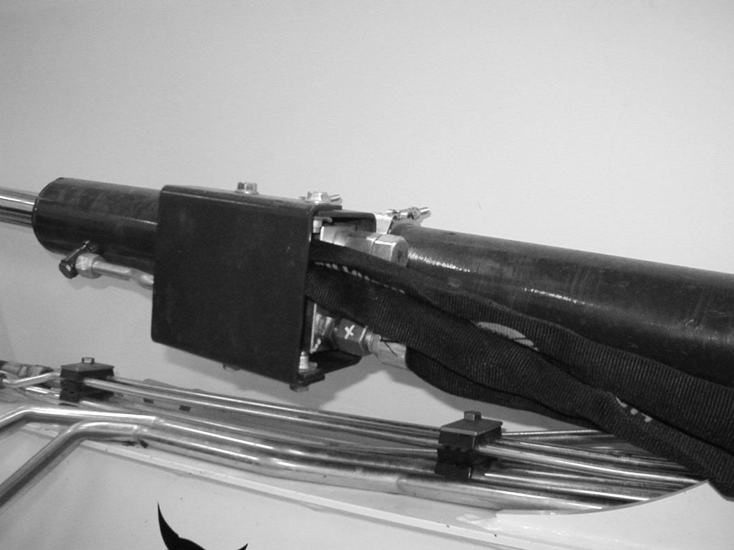
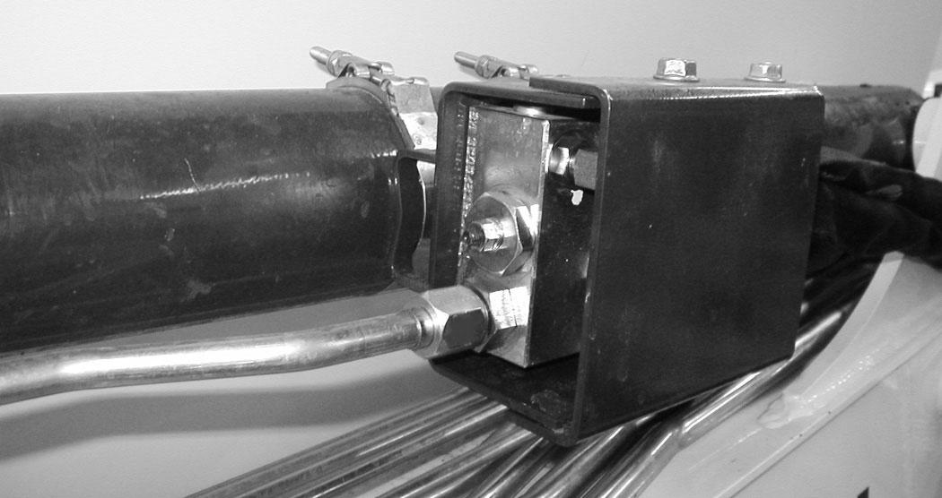
NOTE:DO NOT remove or adjust the two port relief valves (Item 1) [Figure 79]. If the port relief valves have been tampered with, see your Bobcat dealer for service.
Warning
AVOID BURNS
Hydraulic fluid, tubes, fittings and quick couplers can get hot when running machine and attachments. Be careful when connecting and disconnecting quick couplers.

ARM LOAD HOLDING VALVE (CONT’D)
Lowering Arm With Load Holding Valve (Cont’d)
Figure 81
Loss of hydraulic pressure:
Use the same procedure as: With rod end hose failurewith NO accumulator pressure above.
Lowering procedures:
With base end hose failure:
Loosen the locknut (Item 1). Install a hex wrench into the valve screw (Item 2) [Figure 81] and slowly rotate the screw clockwise 1/8 to 1/4 turn and allow the arm to lower.
After the arm is lowered, rotate the screw counterclockwise (Item 2) the same 1/8 to 1/4 turn and tighten the locknut (Item 1) [Figure 81]
With rod end hose failure - with accumulator pressure:
Place a container under the valve and hose end to contain hydraulic fluid. Enter the excavator and turn the key to the ON position or press the ENTER CODE button (Keyless Panel), but do not start the engine. Move the joystick arm retract function to slowly lower the arm.
With rod end hose failure and NO accumulator pressure:
Remove the arm base end hose from the arm load holding valve. Place a container under the valve and base end hose to contain hydraulic fluid.
Loosen the locknut (Item 1). Install a hex wrench into the valve screw (Item 2) [Figure 81] and slowly rotate the screw clockwise 1/8 to 1/4 turn and allow the arm to lower.
After the arm is lowered, rotate the screw (Item 2) counterclockwise 1/8 to 1/4 turn and tighten the locknut (Item 1) [Figure 81]. Reinstall the base end hose.
Daily Inspection
Daily Inspection And Maintenance
Figure 82
Warning
Operator must have instructions before operating the machine. Untrained operators can cause injury or death.
W-2001-0502
Fluids such as engine oil, hydraulic fluid, coolants, etc. must be disposed of in an environmentally safe manner. Some regulations require that certain spills and leaks on the ground must be cleaned in a specific manner. See local, state, and federal regulations for correct disposal.
Important
Pressure Washing Decals
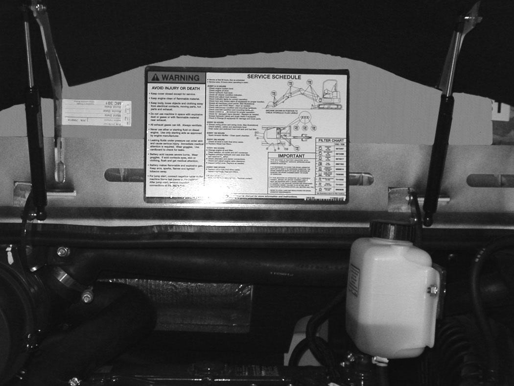
Maintenance work must be done at regular intervals. Failure to do so will result in excessive wear and early failures. The Service Schedule is a guide for correct maintenance of the Bobcat excavator. The decal (Item 1) [Figure 82] is located inside the rear door. (See SERVICE SCHEDULE on Page 153.)
Check the following items before each day of operation:
•Operator Canopy or Cab (ROPS / TOPS) and mounting hardware.
•Seat belt and mounting hardware. Replace seat belt if damaged.
•Check for damaged decals, replace as needed.
•Check control console lockout.
•Check X-Change System (if equipped) for damage or loose parts.
•Air cleaner and intake hoses / clamps.
•Engine oil level and engine for leaks.
•Engine coolant level and engine for leaks.
•Check engine area for flammable materials.
•Check hydraulic fluid level and system for leaks.
•Check indicator lights for correct operation.
•Grease all pivot points.
•Check cylinder and attachment pivot points.
•Check the track tension.
•Repair broken and loose parts.
•Check or clean cab heater filters (if equipped).
•Check front horn and motion alarm (if equipped) for proper function.
•Never direct the stream at a low angle toward the decal that could damage the decal causing it to peel from the surface.
•Direct the stream at a 90 degree angle and at least 300 mm (12 in) from the decal. Wash from the center of the decal toward the edges.
I-2226-0910
Important
This machine is factory equipped with a U.S.D.A. Forestry Service approved spark arrester exhaust system.
The spark arrester muffler, if equipped, must be cleaned to keep it in working condition. The spark arrester muffler must be serviced by dumping the spark chamber every 100 hours of operation.
On some models, the turbocharger functions as the spark arrester and must operate correctly for proper spark arrester function.
If this machine is operated on flammable forest, brush, or grass covered land, it must be equipped with a spark arrester attached to the exhaust system and maintained in working order. Failure to do so will be in violation of California State Law, Section 4442. PRC. Refer to local laws and regulations for spark arrester requirements.
I-2284-0111
PRE-STARTING PROCEDURE
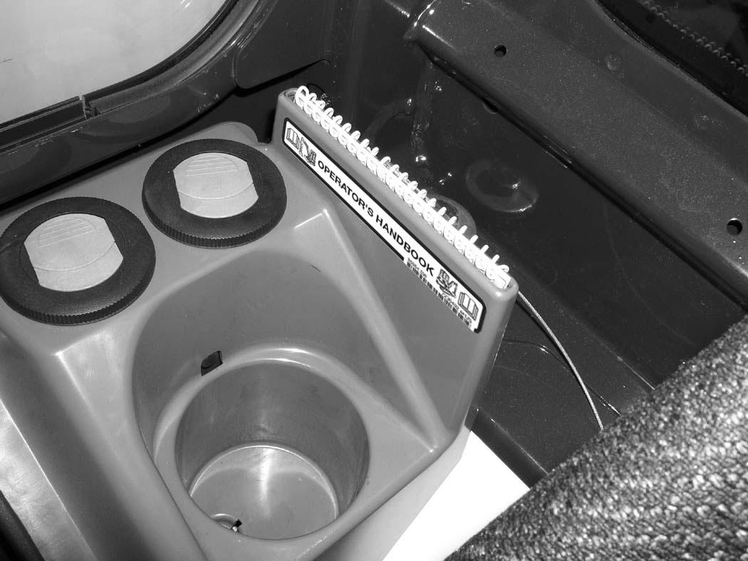
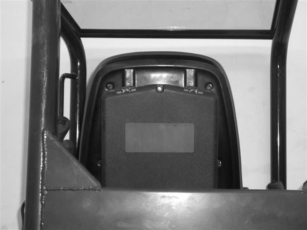
Operation & Maintenance Manual And Operator’s Handbook Locations
83
Entering The Excavator
Warning
AVOID INJURY OR DEATH
Instructions are necessary before operating or servicing machine. Read and understand the Operation & Maintenance Manual, Operator’s Handbook and signs (decals) on machine. Follow warnings and instructions in the manuals when making repairs, adjustments or servicing. Check for correct function after adjustments, repairs or service. Untrained operators and failure to follow instructions can cause injury or death.
W-2003-0807
Read and understand the Operation & Maintenance Manual (Item 1) [Figure 83] (located inside the storage box on the back of the operator’s seat) and the Operator’s Handbook (Item 1) [Figure 84] before operating.